
Memory system with cyclic redundancy check

a memory system and check box technology, applied in the field of memory system with cyclic redundancy check, can solve the problems of increasing the pin count, unacceptable system failure, and memory system not providing the ability to detect errors in transmitted addresses

Inactive Publication Date: 2011-10-18
POLARIS INNOVATIONS LTD
View PDF5 Cites 32 Cited by
  • Summary
  • Abstract
  • Description
  • Claims
  • Application Information

AI Technical Summary

Benefits of technology

"The present invention is related to a memory system that includes a memory controller and a memory module for transferring data signals and address signals between them. The system includes an address register for pre-storing an address signal for a data block to be transferred and a cyclic redundancy checksum calculator for calculating a checksum for the data block. The pre-stored address signal is used as an initial value for the checksum calculation. The technical effect of this invention is to provide a reliable and efficient mechanism for transferring data signals and address signals between the memory controller and the memory module while ensuring error securing."

Problems solved by technology

As graphics systems store more and more code in the DRAM, effective error detection becomes essential, as random bit fails associated with any high speed data transmission would lead to unacceptable system failures.
Until now, such memory systems have not provided the ability to detect errors in the transmitted addresses without using an additional pin at the controller module and / or the memory module.
However the additional pin at the controller module and / or the memory module disadvantageously increases the pin count as well as the power consumption at the controller module and / or the memory module.

Method used


Image

  • Memory system with cyclic redundancy check
  • Memory system with cyclic redundancy check
  • Memory system with cyclic redundancy check

Examples


Embodiment Construction

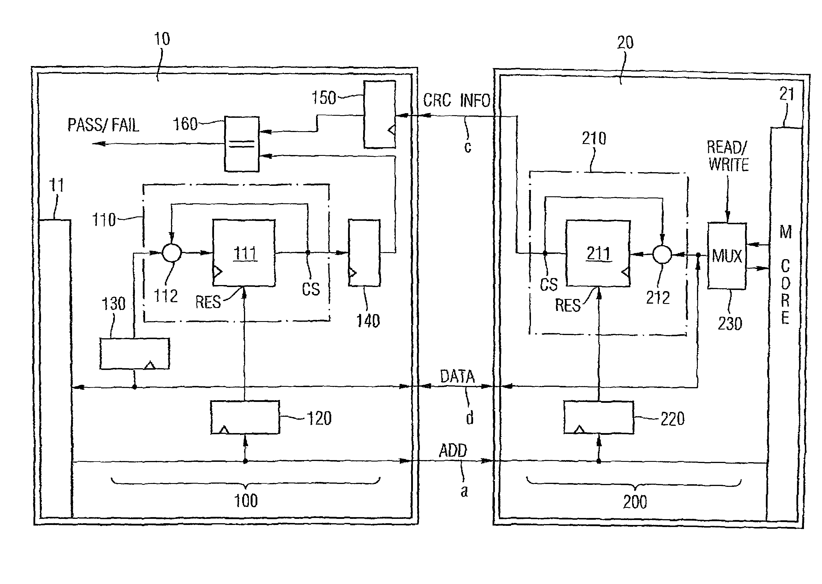
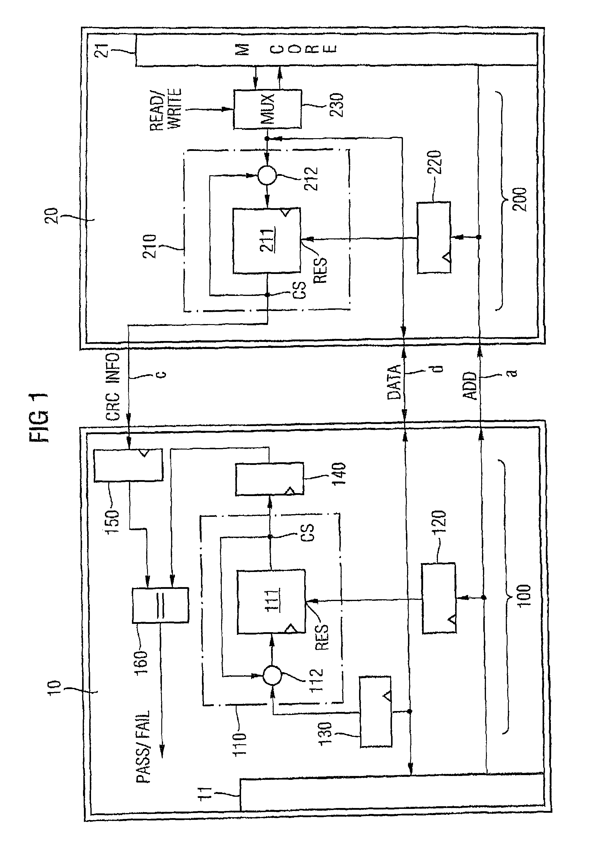
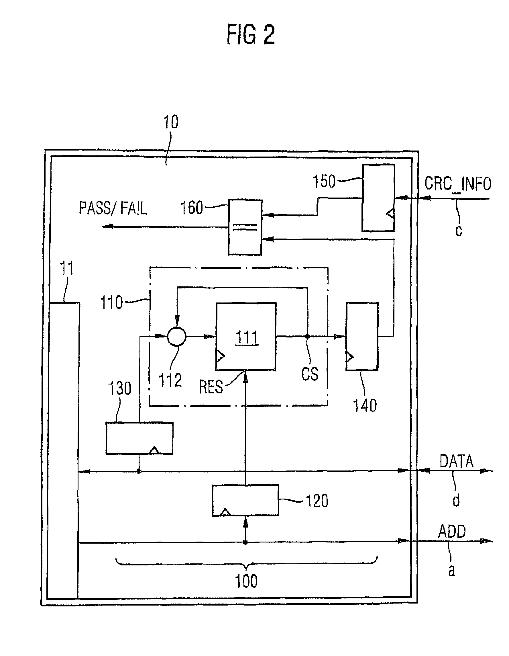
According to the embodiment depicted in FIG. 1, a memory system according to one embodiment comprises a memory controller 10 and a memory module 20. The memory controller 10 and the memory module 20 includes a cyclic redundancy check (CRC) calculator 100, 200 configured to calculate a CRC error recognition checksum for at least one block of data and address signals to be transferred within at least one signal frame between the memory controller 10 and the memory module 20. The CRC calculator 100, 200 includes: an address register 120, 220 configured to pre-store an address signal ADD associated to a corresponding at least one block of data signals to be transferred, and a CRC generator 110, 210 being configured to calculate the CRC error recognition checksum upon being initiated by the pre-stored address signal ADD.

The memory controller 10 sends blocks of write data signals to and receives blocks of read data signals DATA from the memory module 20 through data signal lines d. The me...


PUM


Abstract

A memory system, with a memory controller and a memory module, is configured to transfer error securing data and address signals within signal frames between the memory controller and the memory module. The memory system includes: an address register configured to pre-store an address signal associated with at least one block of data signals to be transferred, and at least one cyclic redundancy checksum calculator included in one of the memory controller and the memory module, the calculators being configured to calculate a cyclic redundancy checksum for the at least one data signal block, wherein the pre-stored address signal is used as an initial value for the calculation of the cyclic redundancy checksum and the at least one block of data and address signals are transferred together with the calculated cyclic redundancy checksum.

Description

BACKGROUNDFor detecting transmission errors occurring on high speed signal lines, a standard for future graphic memory systems (e.g., the Graphic Double Data Rate 5 (GDDR5) standard) envisages an error detection on the data bus to improve system reliability. As graphics systems store more and more code in the DRAM, effective error detection becomes essential, as random bit fails associated with any high speed data transmission would lead to unacceptable system failures.In the GDDR5 standard, the transmitted data is secured using a CRC (cyclic redundancy check) with an algorithm that is well established within high quality communication environments like ATM networks. The algorithm enables a detection of most errors with 100% probability. Error detection can be used to trigger retraining of the data transmission line which allows the system to dynamically adapt to changing conditions (e.g., temperature or voltage drift).Until now, such memory systems have not provided the ability to ...

Claims


Application Information

Patent Timeline
Patent Type & Authority Patents(United States)
IPC IPC(8): G11C29/00
CPCG06F11/1004
Inventor BALB, MARKUS
Owner POLARIS INNOVATIONS LTD
Learn More