Electric power steering device

a technology of electric power steering and gears, which is applied in the direction of bearing unit rigid support, bearings, transportation and packaging, etc., can solve the problems of increasing assembly costs, easy generation of abnormal noise from gears, and increasing number of components, so as to reduce manufacturing costs, reduce assembly labor, and suppress abnormal noise from idle gears

Active Publication Date: 2011-10-25
JTEKT CORP
View PDF22 Cites 9 Cited by
  • Summary
  • Abstract
  • Description
  • Claims
  • Application Information

AI Technical Summary

Benefits of technology

[0005]However, the reducer includes three gears, and thus, the number of components tends to increase, and by extension, the assembly cost tends to increase. Also, abnormal noise resulting from the gears easily occurs.
[0006]Therefore, an object of the present invention is to provide an electric power steering apparatus that is capable of suppressing abnormal noise and that is inexpensive.Means for Solving the Problem
[0008]In this mode, when the synthetic resin member in which the idle gear is arranged is molded, the molding of the synthetic resin member and the fixing of the idle gear to the outer ring can be achieved collectively. Thus, labor for assembly can be alleviated. As a result, manufacturing cost can be decreased. Further, due to a vibration-prevention effect of the synthetic resin member, the generation of abnormal noise associated with the idle gear can be suppressed.

Problems solved by technology

However, the reducer includes three gears, and thus, the number of components tends to increase, and by extension, the assembly cost tends to increase.
Also, abnormal noise resulting from the gears easily occurs.

Method used


Image

  • Electric power steering device
  • Electric power steering device
  • Electric power steering device

Examples


Embodiment Construction

[0032]Hereinafter, an embodiment of the present invention will be described in detail with reference to the accompanying drawings.

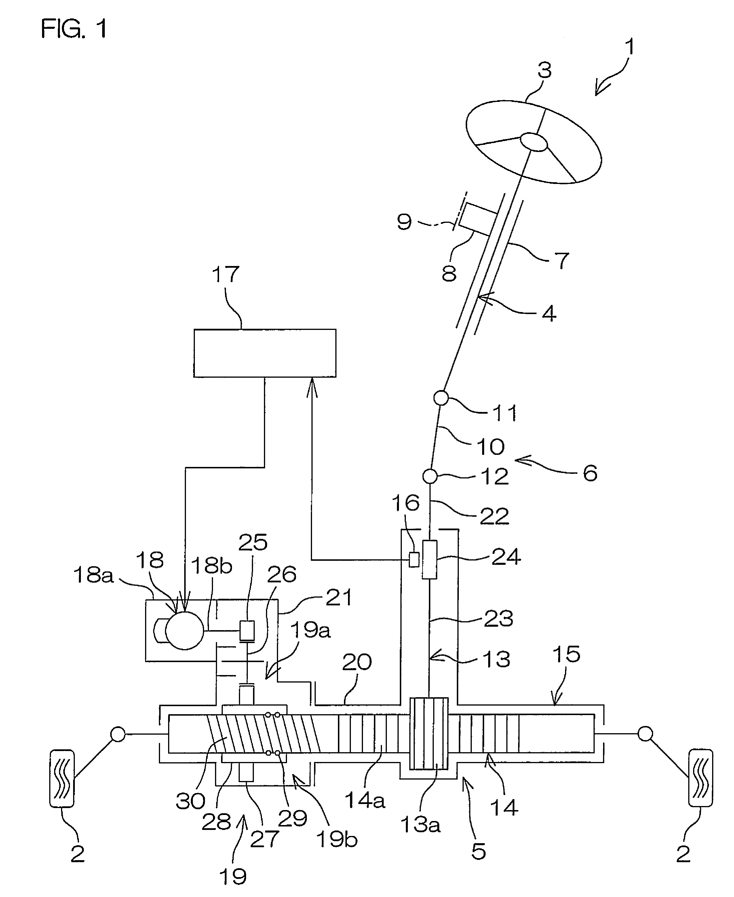
[0033]FIG. 1 is a schematic diagram of an electric power steering apparatus of one embodiment of the present invention. An electric power steering apparatus 1 includes: a steering shaft 4 for transmitting a steering torque applied to a steering wheel 3 as a steering member for steering a steerable wheel 2; a steering mechanism 5, composed of a rack-and-pinion mechanism, for example, for steering the steerable wheel 2 by the steering torque from the steering shaft 4; and an intermediate shaft 6 that is arranged between the steering shaft 4 and the steering mechanism 5 and that serves as a coupling for transmitting rotation therebetween.

[0034]The steering shaft 4 inserts through the interior of a steering column 7 and is supported rotatably by the steering column 7. The steering column 7 is supported by a vehicle body 9 via a bracket 8. One end of the steer...


PUM


Abstract

A parallel shaft gear mechanism (19a) for a steering assist of the present electric power steering apparatus (1) includes an idle gear (26) rotatably supported via a rolling bearing (39), on an outer peripheral surface (37d) of an intermediate shaft (37) supported by a rack housing (15). The idle gear (26) is arranged in an annular synthetic resin member (43) fixed on the outer peripheral surface (44a) of an outer ring (44) of the bearing (39). On the outer peripheral surface (44a) of the outer ring (44), a regulating portion (53, 53A, 53B, 53C, 53D, 53E, 53F, 53G, 54, 54A, 54B, 54C, 54D, 54E, 54F, 55, 56, 56A, 56B, 59, 59A, and 59B) for regulating relative rotation between the outer ring (44) and the synthetic resin member (43) is arranged. The synthetic resin member (43) is formed in a manner to cover the regulating portion on the outer peripheral surface (44a) of the outer ring (44), as a result of a molding process using a mold.

Description

TECHNICAL FIELD[0001]The present invention relates to an electric power steering apparatus.PRIOR ART[0002]Electric power steering apparatuses include an electric power steering apparatus of a so-called rack assist type. This type of electric power steering apparatus includes an electric motor for a steering assist, a reducer, and a ball thread mechanism. The ball thread mechanism includes a ball thread shaft and a nut. The ball thread shaft is connected to a rack bar of a rack pinion-type steering mechanism. Output of the electric motor is transmitted via the reducer and the ball thread mechanism, to the rack bar, and as a result, the rack bar is linearly moved (for example, see Patent Document 1).[0003]In Patent Document 1, the reducer includes three gears, i.e., a drive gear, an intermediate gear, and a driven gear. When the electric motor drives the drive gear, the rotation of the drive gear is transmitted via the intermediate gear to the driven gear, and the driven gear drives a...

Claims


Application Information

Patent Timeline
Patent Type & Authority Patents(United States)
IPC IPC(8): B62D5/04
CPCB62D5/0424F16C33/04F16C35/02F16H55/06Y10T74/19828F16H55/17F16H2055/065F16C2361/61
Inventor KUROKAWA, TAKANORI
Owner JTEKT CORP
Why Eureka
Try Eureka