Actuator

a technology of actuators and actuators, applied in the field of actuators, can solve the problems of limiting the potential of shape memory material deformation to be used, and reducing the efficiency of actuation,

Active Publication Date: 2011-10-25
ROLLS ROYCE PLC
View PDF22 Cites 9 Cited by
  • Summary
  • Abstract
  • Description
  • Claims
  • Application Information

AI Technical Summary

Benefits of technology

[0015]Potentially, the slide elements provide a lateral stiffness in an actuator structure.
[0016]Possibly, the actuator incorporates an encapsulated wax to provide structural rigidity.

Problems solved by technology

The spacing pedestals secured to the shape memory alloy create stress rising features and so do not allow the full potential of the shape memory material deformation to be utilised for actuation.
Previous approaches have generally implied a necessity to achieve a two dimensional design and loading structure whilst certain situations require a three dimensional application such as changing an air flow direction or aperture size so that consideration must be made to utilisation of a faster design which in turn is less efficient.

Method used


Image

  • Actuator
  • Actuator
  • Actuator

Examples


second embodiment

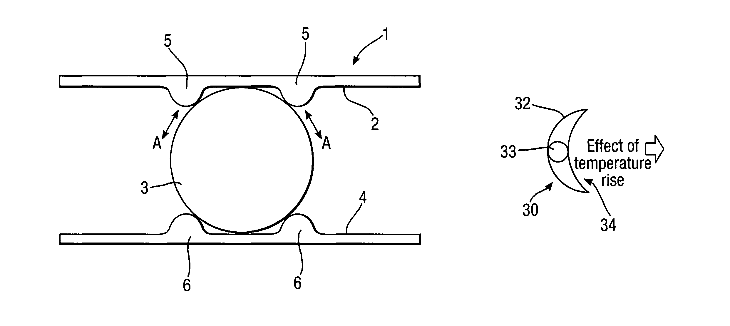
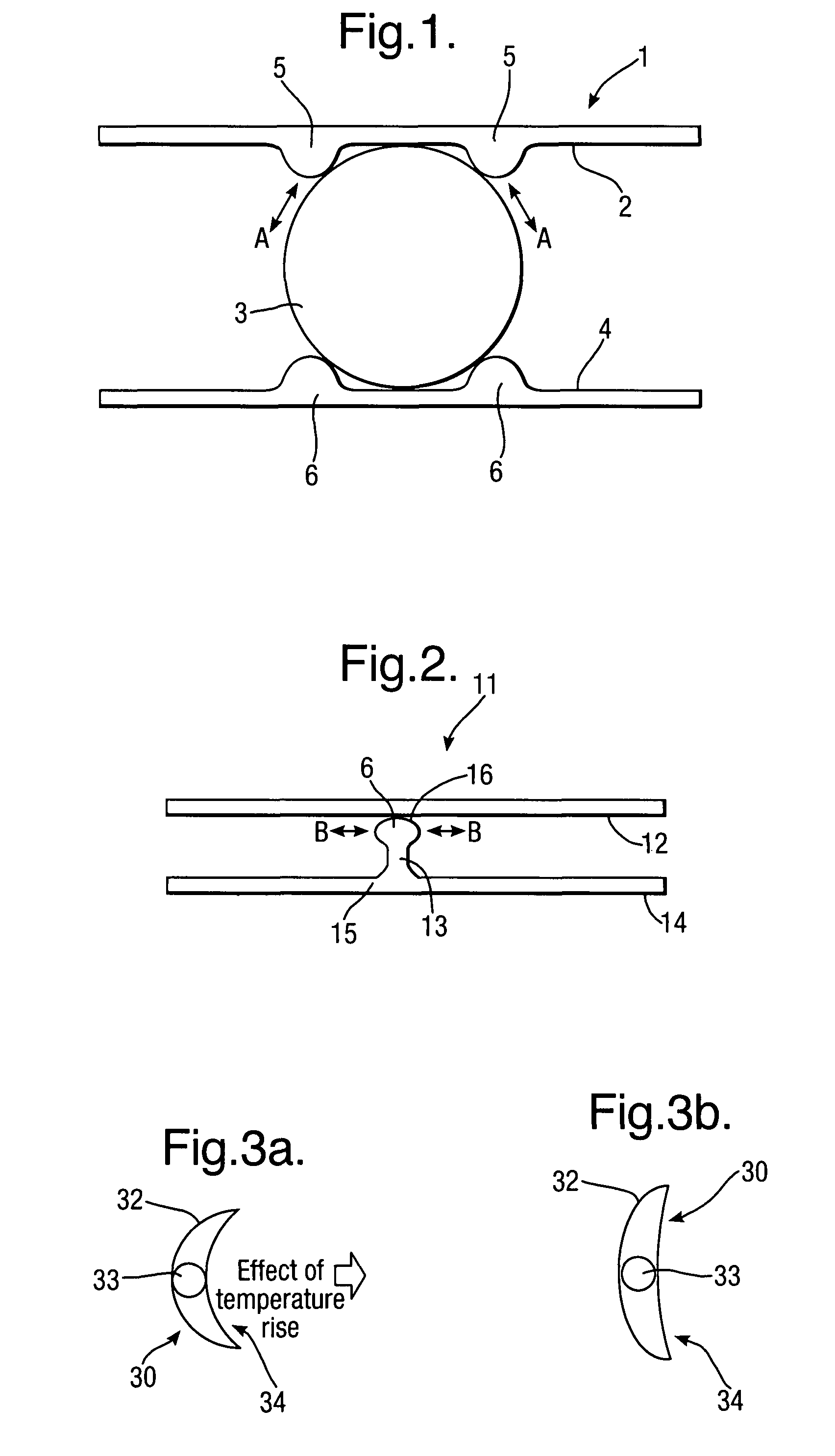
[0041]FIG. 2 provides a schematic cross section of a second actuator 11 in accordance with aspects of the present invention. In this second embodiment of an actuator 11 a flat shape memory alloy layer 12 slides relative to a pedestal portion 13 extending from a spring material layer 14. It will be understood that the pedestal is formed with an appropriate fillet radii 15 and central section in the form of a bulbous end 16 such that the pedestal 13 is appropriately presented and the bulbous end 16 allows bending of the shape memory alloy layer 12 thereabouts. Again, the shape memory alloy material will slide in the direction of arrowheads B such that spacing between the shape memory alloy layer 12 and the presenting spring material layer 14 is retained whilst thermal contact, as well as constraint of the layer 12, is limited.

[0042]The second embodiment depicted in FIG. 2 can be considered a rocker pedestal arrangement in view of the necessary bulbous end or other rounded aspects to t...

third embodiment

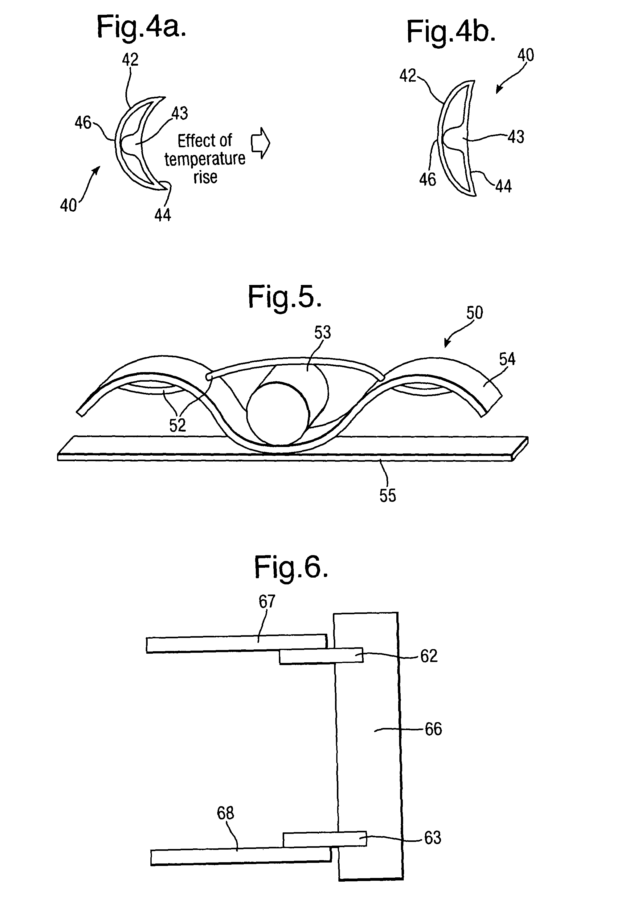
[0060]FIG. 5 illustrates an actuator in accordance with aspects of the present invention. This actuator 50 comprises a shape memory alloy fibre or fibre bundle 52 interleaved with a bias in the form of a corrugated spring 54 with a spacer 53 in the form of a roller. The roller 53 will generally incorporate notches or grooves to guide and present the shape memory alloy fibre or wire 52. In such circumstances, the shape memory alloy wire and bias spring 54 are in an antagonistic relationship such that expansion or contraction of the shape memory alloy fibre 52 causes alterations in the configuration of the actuator whilst the spring 54 returns the actuator to a base state dependent upon the shape memory alloy condition. Optionally, a stiffening surface 55 may be added to provide a mounting for the actuator arrangement.

[0061]In use the shape memory alloy fibre or cable 52 may be attached to a device which requires actuation. In such circumstances, dependent upon the thermal cycle, the ...

fifth embodiment

[0066]FIGS. 8 and 9 respectively illustrate use of an actuator in accordance with aspects of the present invention located within the trailing edge of a blade or vane of a gas turbine engine. FIG. 8 illustrates schematically a cross section such that an actuator 71 is located towards a trailing edge of the blade 70. The actuator 71 comprises a bimetallic titanium / shape memory alloy located appropriately in order to alter and deform over a temperature cycle. Typically, an additional length 72 of the actuator is provided to generate more force with respect to the shape memory alloy. An opposed surface 73 has a lower stiffness projecting to an air washed surface 74. In such circumstances, rollers or other slide elements 75 are provided within the actuator 71 in order that the shape memory alloy deforms over its thermal range, the rollers or other slide elements provide necessary deformation of the trailing edge of the blade 70 whilst avoiding stress differentiation across the actuator ...


PUM

PropertyMeasurementUnit
transition temperaturesaaaaaaaaaa
depthaaaaaaaaaa
depthaaaaaaaaaa

Abstract

Actuators utilising shape memory alloy materials are known with regard to gas turbine engines. Such shape memory alloys have been used with respect to deformation provided in vanes and blades as well as nozzle elements in order that variations can be made in engine configuration dependent upon thermal cycling. Unfortunately, pedestals in order to provide spacing between the shape memory alloy and an antagonistic bias has resulted in uneven stress distribution as well as a higher thermal mass for the shape memory alloy. An uneven stress distribution will limit operational life whilst a higher thermal mass will result in slower reaction times. By separation of the shape memory alloy or material from its antagonistic bias through use of a slide element, a reduction in thermal mass is achieved and, more importantly, stress differentiation across the actuator is reduced.

Description

CROSS-REFERENCE TO RELATED APPLICATIONS[0001]This application claims foreign priority to United Kingdom Patent Application No. GB 0614114.7, filed 15 Jul. 2006.BACKGROUND OF THE INVENTION[0002]The present invention relates to actuators and more particularly to actuators utilised within gas turbine engines in order to vary blade or vane or nozzle tab configuration.[0003]Use of shape memory materials such as shape memory alloys is well known in order to achieve variation in dimensions or actuation by such deformation. Typically, the shape memory alloy or material acts against a bias in the form of a mechanical spring. An example of a prior use of shape memory materials is given in U.S. Pat. No. 6,813,877 in relation to nozzle tabs and fins adjustable dependent upon exit temperatures from a gas turbine engine.[0004]Generally, a spacing pedestal must be provided between the shape memory alloy or material. The spacing pedestals secured to the shape memory alloy create stress rising featu...

Claims


Application Information

Patent Timeline
Patent Type & Authority Patents(United States)
IPC IPC(8): F01D21/12
CPCF01D5/148F01D7/00F01D9/041F01D17/16F05D2300/505
Inventor CLARK, DANIELWEBSTER, JOHN R
Owner ROLLS ROYCE PLC
Why Eureka
Try Eureka