Modular HVDC converter

a converter and module technology, applied in the field of high voltage direct current converter systems, can solve the problems of increasing the size increasing the cost of local power supplies, and increasing the cost of offshore manning, so as to achieve the effect of small size, improved redundancy, and simple handling

Active Publication Date: 2011-10-25
HITACHI ENERGY LTD
View PDF14 Cites 13 Cited by
  • Summary
  • Abstract
  • Description
  • Claims
  • Application Information

AI Technical Summary

Benefits of technology

[0011]Each one of the modular converters is small sized and light compared to conventional converters, thereby the handling will be simpler, especially handling during maintenance and reparations.
[0012]The modular approach gives considerably better redundance compared with conventional converters, as the failure of one converter will not lead to full loss of electrical power, and loads connected to other converters will not be affected.

Problems solved by technology

Feeding power to or from remote or awkwardly situated distributed installations from or to an existing power network creates slightly different challenges compared to normal installations.
However, such local power supplies require considerably space and offshore manning.

Method used


Image

  • Modular HVDC converter
  • Modular HVDC converter
  • Modular HVDC converter

Examples


Embodiment Construction

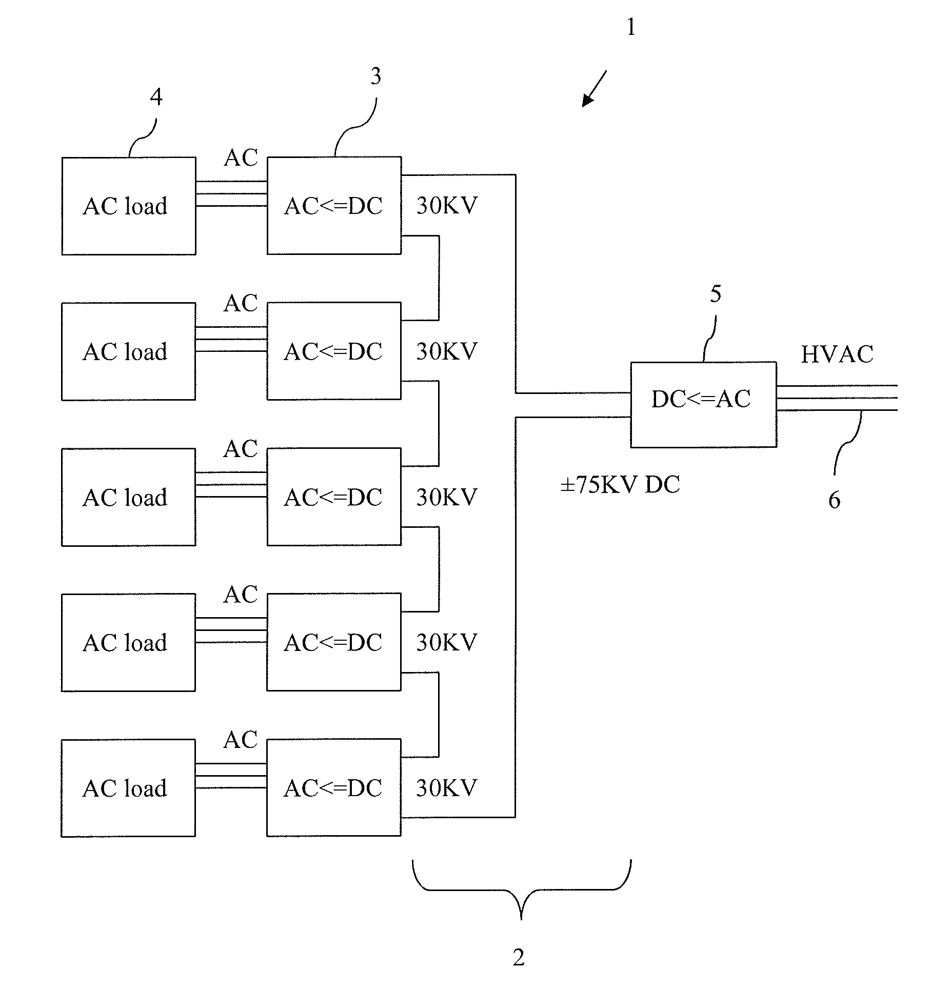
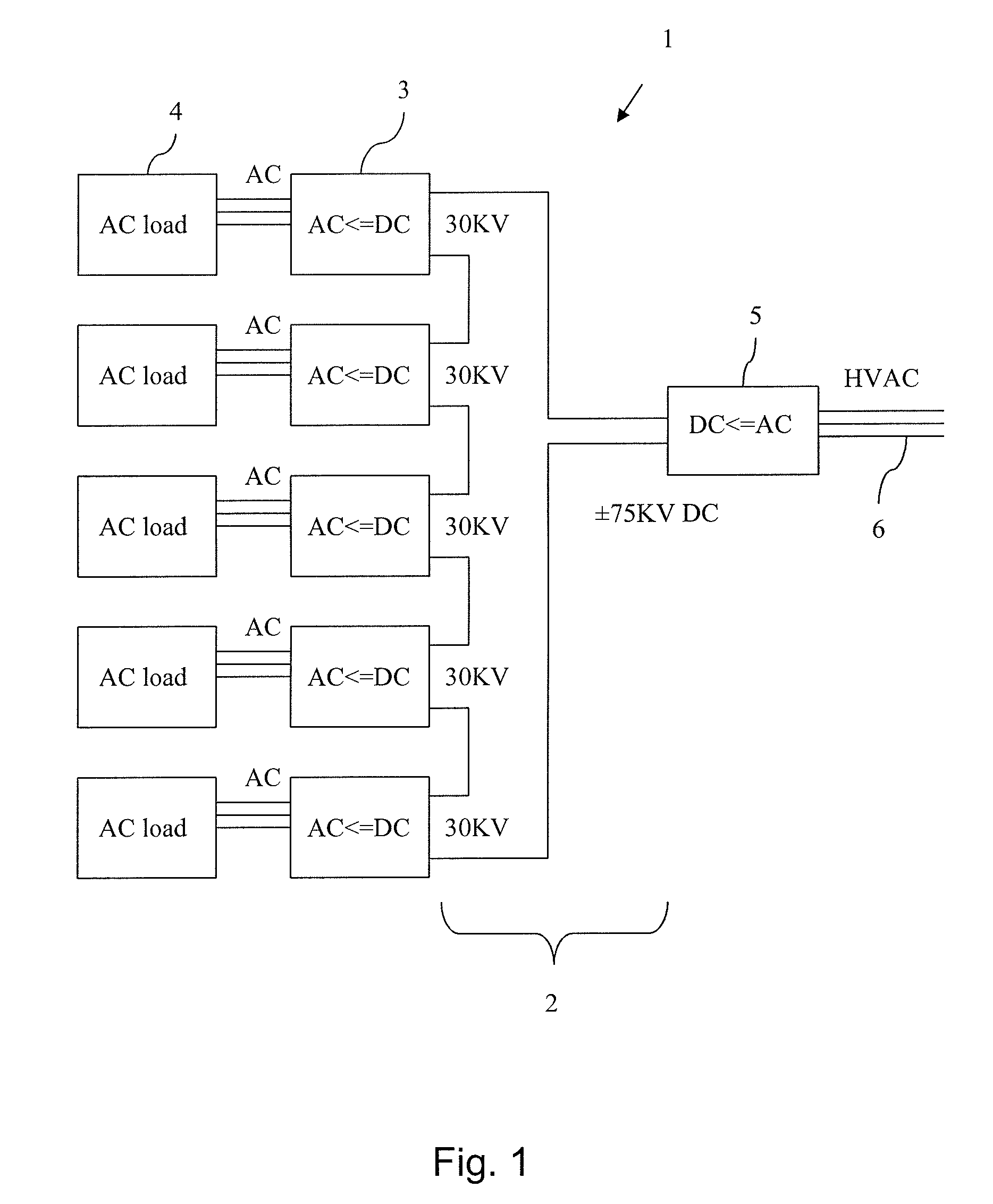
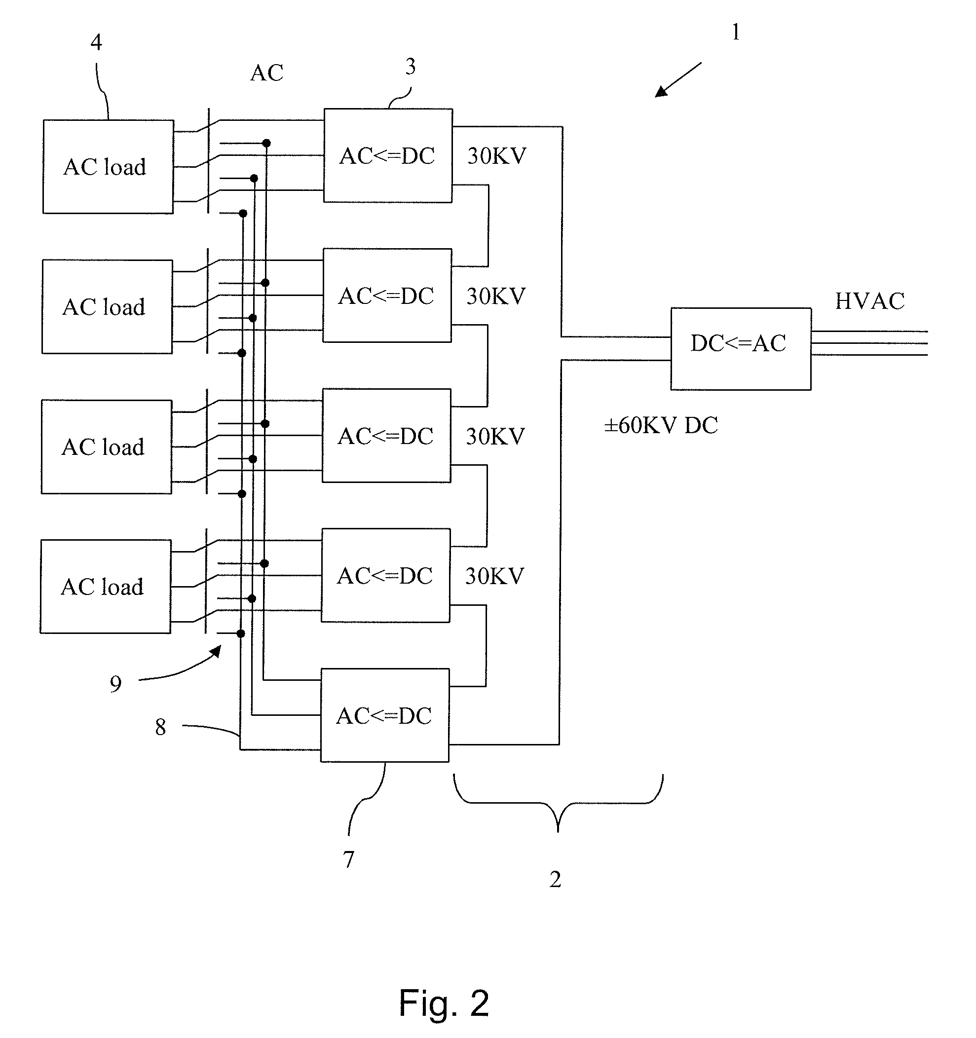
[0027]FIG. 1 schematically shows one embodiment of a modular HVDC converter system 1 according to the present invention. The modular HVDC converter system 1 comprises, a High Voltage Direct Current (HVDC) network 2, two or more DC / AC converters 3 being connected in series to the HVDC network, wherein each one of the DC / AC converters is arranged to provide AC to a separate AC load 4. The modular converter is built up of a number of small sized series connected converter units 3, each controlled individually. Failure of one converter will not stop the entire transmission as the others will continue to operate as normal. The converter units 3 are connected in series, and assuming an ideal situation wherein they represent identical loads in the HVDC circuit 2, the voltage across each converter unit will be approximately the HVDC voltage divided with the number of active converters. HVDC is supplied to the HVDC network e.g. by a rectifier station arranged to supply a constant current (Id...


PUM


Abstract

A modular HVDC converter system including a high voltage direct current network, and at least two DC / AC converters being connected in series to the HVDC network. Each of the DC / AC converters is arranged to provide AC to a separate AC load.

Description

CROSS-REFERENCE TO RELATED APPLICATIONS[0001]This application is the national phase under 35 U.S.C. §371 of PCT / SE2006 / 050226 filed 28 Jun. 2006.THE FIELD OF THE INVENTION[0002]The present invention relates to a High Voltage Direct Current (HVDC) converter system and in particular a modular HVDC converter system its components and use thereofBACKGROUND OF THE INVENTION[0003]Feeding power to or from remote or awkwardly situated distributed installations from or to an existing power network creates slightly different challenges compared to normal installations. This is especially true for installations with several high power sources or loads. Examples of such remote or awkwardly situated distributed installations are offshore installations for oil and / or gas production especially installations sub sea, offshore wind mill installations, and mining districts or process plants at remote locations.[0004]As is disclosed in EP 1385259, WO 0152379 and WO 0148892 it is favorable to use HVDC ...

Claims


Application Information

Patent Timeline
Patent Type & Authority Patents(United States)
IPC IPC(8): H02J1/00H02M1/00H02M1/32H02M7/5387
CPCH02M7/7575H02M2001/0074Y10T307/406Y10T307/707Y02E60/60H02J3/36H02M7/003H02M7/162H02M7/19H02M7/5387H02M1/0074H02M1/325
Inventor ASPLUND, GUNNARHYTTINEN, MATS
Owner HITACHI ENERGY LTD
Why Eureka
Try Eureka