
Antenna system having electromagnetic bandgap

an antenna system and electromagnetic bandgap technology, applied in the direction of resonant antennas, antenna adaptation in movable bodies, radiating elements structural forms, etc., can solve the problem that the electromagnetic bandgap is not applied to the base station antenna, and achieve the effect of reducing back radiation, improving performance, and reducing manufacturing and installation costs

Inactive Publication Date: 2011-10-25
ELECTRONICS & TELECOMM RES INST
View PDF10 Cites 1 Cited by
  • Summary
  • Abstract
  • Description
  • Claims
  • Application Information

AI Technical Summary

Benefits of technology

[0009]In view of the above, the present invention provides an antenna system having an electromagnetic bandgap to which the electromagnetic bandgap is applied to a metal surface that would deteriorate wave radiation efficiency of an antenna so that an overall size of the antenna can be reduced using unique electromagnetic characteristics of the electromagnetic bandgap, and back radiation of the antenna system can be reduced to improve directivity in the main forward radiation direction of the antenna system.
[0022]The base station antenna, the repeater antenna, the satellite-tracking antenna, and the vehicle antenna, respectively having an electromagnetic bandgap, in accordance with the present invention, may exhibit improved performance over the existing antenna system in size, directivity, and radiation efficiency. In the base station antenna, the repeater antenna, and the satellite-tracking antenna, the antenna systems are miniaturized so that costs for manufacturing and installing thereof can be reduced, the back radiation is reduced, and the directivity can be improved in the main beam direction. Since the vehicle antenna has improved radiation characteristics using the electromagnetic bandgap, a system having an improved reception such as a vehicle radio, a navigation system, a television and the like can be implemented.

Problems solved by technology

However, the electromagnetic bandgap is not being applied to a base station antenna, a repeater antenna, a satellite-tracking antenna, a vehicle antenna, and the like, yet.

Method used


Image

  • Antenna system having electromagnetic bandgap
  • Antenna system having electromagnetic bandgap
  • Antenna system having electromagnetic bandgap

Examples


Embodiment Construction

[0037]Hereinafter, embodiments of the present invention will be described in detail with reference to the accompanying drawings. In the following description of the present invention, if the detailed description of the already known structure and operation may confuse the subject matter of the present invention, the detailed description thereof will be omitted.

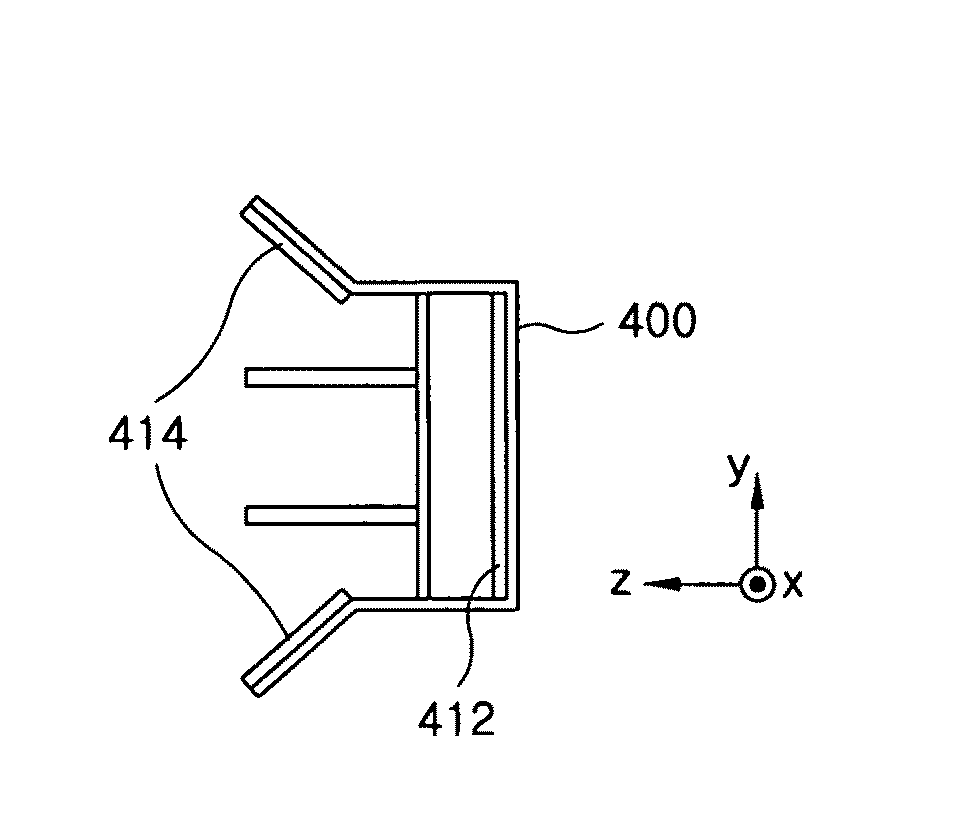
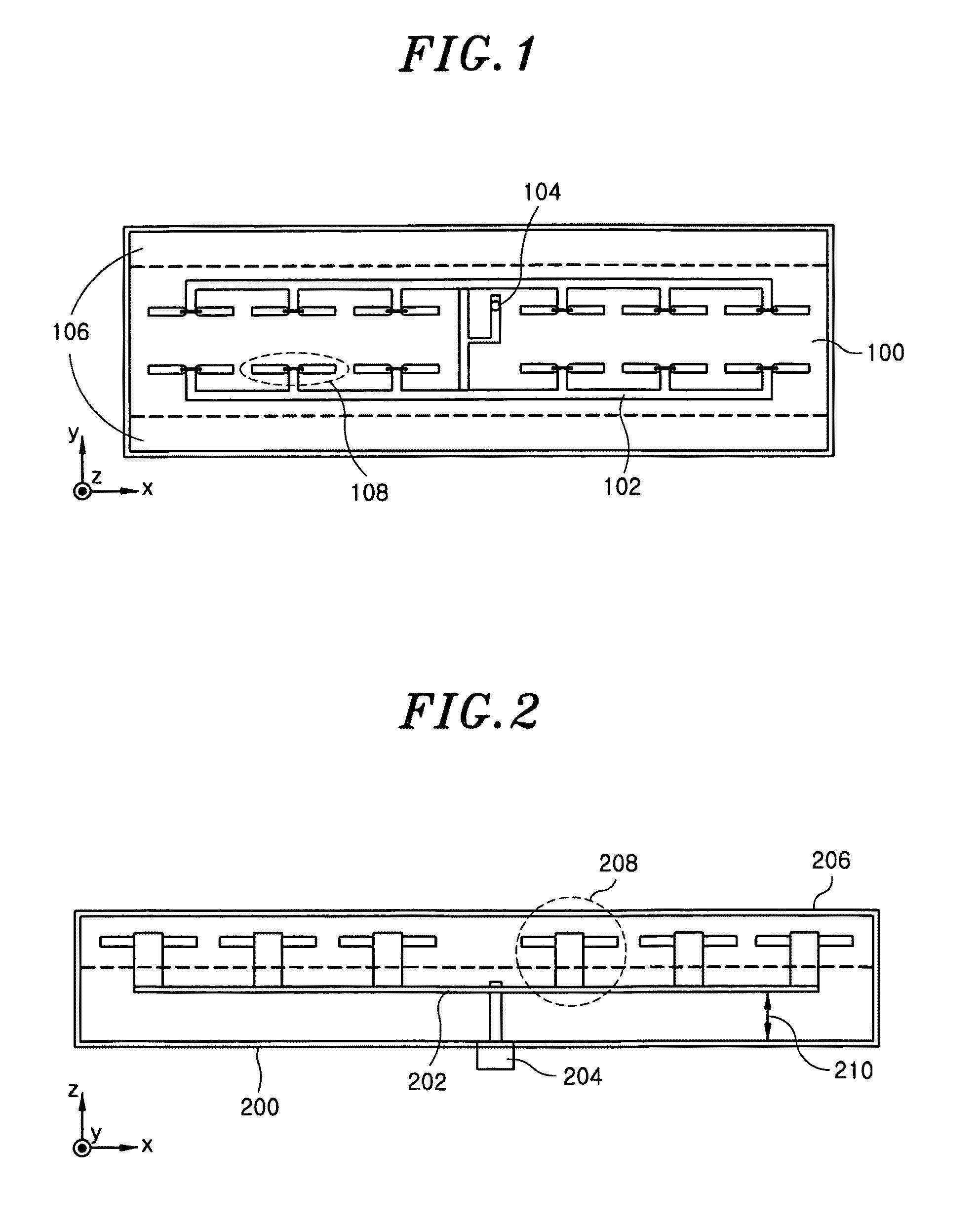
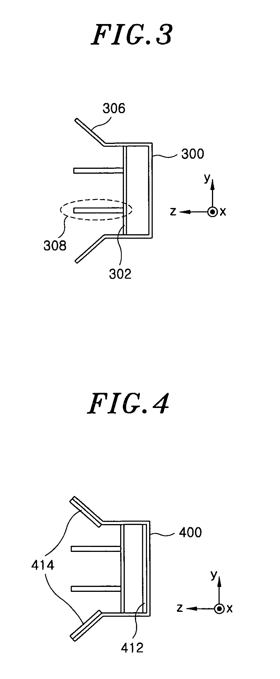
[0038]FIGS. 1 to 3 are a plane view, a front view, and a side view respectively illustrating a base station antenna system. As illustrated in FIGS. 1 to 3, the base station antenna system includes dipole antennas 108, 208, and 308 transmitting and receiving an RF signal, power feeding lines 102, 202, 302, feeding electric power to the dipole antennas 108, 208, and 308 and serving as a power distributor, and grounds 100, 200, 300, and 400 of metal conductors electrically connected to the power feeding lines 102, 202, and 302 to ground the dipole antennas 108, 208, and 308. The base station antenna system further includes reflec...


PUM


Abstract

An antenna system includes an antenna transmitting and receiving a signal; a power feeding line feeding electric power to the antenna; and a metal conductor ground electrically connected to the power feeding line. Further, the metal conductor ground includes an electromagnetic bandgap.

Description

CROSS-REFERENCE TO RELATED APPLICATIONS[0001]The present invention claims priority of Korean Patent Application No. 10-2007-0132737, filed on Dec. 17, 2007, which is incorporated herein by reference.FIELD OF THE INVENTION[0002]The present invention relates to an antenna system, and more particularly to an antenna system having an electromagnetic bandgap and employed in a base station, a repeater, a satellite tracking antenna, a vehicle antenna, and the like.[0003]This work was supported by the IT R&D program of MIC / IITA [2007-F-043-01, Study on Diagnosis and Protection Technology based on EM].BACKGROUND OF THE INVENTION[0004]An electromagnetic bandgap can be implemented by periodically arranging desired unit cells on an electric conductor by a preset interval or without the preset interval therebetween, and on the surfaces of arrangements of the unit cells, tangent component of a magnetic field becomes ‘0’ (zero) at a specific band so that an electric current cannot flow on the surf...

Claims


Application Information

Patent Timeline
Patent Type & Authority Patents(United States)
IPC IPC(8): H01Q1/24
CPCH01Q1/1271H01Q1/246H01Q21/062H01Q21/064H01Q21/065H01Q15/006H01Q1/24H01Q1/38
Inventor SIM, DONG-UKKWON, JONG HWAKWAK, SANG ILCHOI, HYUNG DO
Owner ELECTRONICS & TELECOMM RES INST
Learn More