
Semiconductor transformers

a transformer and semiconductor technology, applied in the direction of transformers/inductance coils/windings/connections, fixed transformers or mutual inductances, transformers/inductance coils/windings/connections, etc., can solve the problem of high mechanical stress on the metal-semiconductor interface, easy to break away tracks from the interface, and the requirement of metallic materials on semiconductors. achieve the effect of increasing the thermal expansion coefficient and increasing the conductivity of tracks

Active Publication Date: 2011-11-01
CITY UNIVERSITY OF HONG KONG
View PDF5 Cites 47 Cited by
  • Summary
  • Abstract
  • Description
  • Claims
  • Application Information

AI Technical Summary

Benefits of technology

[0006]The highly doped conducting paths may include silicides or salicides in order to increase the conductivity of the tracks without substantially increasing the thermal expansion coefficients.

Problems solved by technology

In general, transformers are located in circuit boards as separate components and cannot be integrated into semiconductor based integrated circuits.
Thus, the coreless planar transformer concept is still restricted by the use of metallic conductors as the base for the transformer windings, and although a method of integrating magnetic components such as transformers and inductors into semiconductor circuits has been proposed [15], the deposit of metallic materials on semiconductor (and the requirement of a metal-semiconductor interface) is a costly, difficult and complicated process.
This huge difference in thermal expansion coefficients can result in high mechanical stress on the metal-semiconductor interface and the metallic tracks can easily break away from the interface under thermal expansion.

Method used


Image

  • Semiconductor transformers
  • Semiconductor transformers
  • Semiconductor transformers

Examples


Embodiment Construction

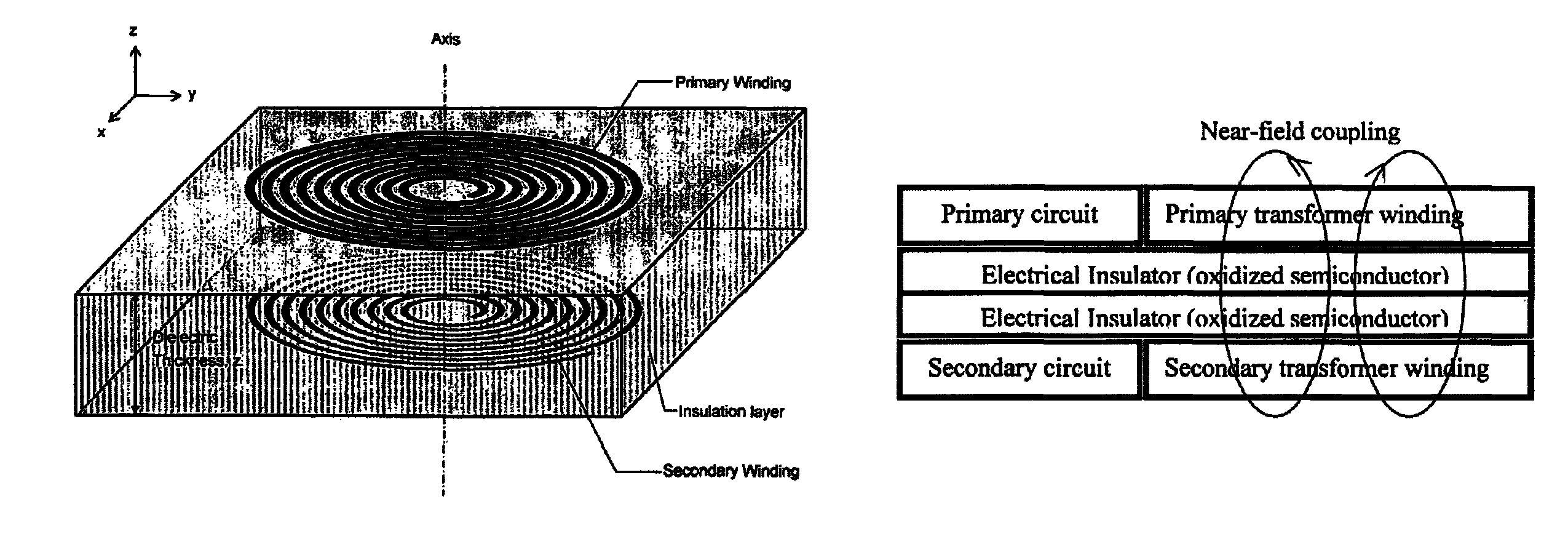
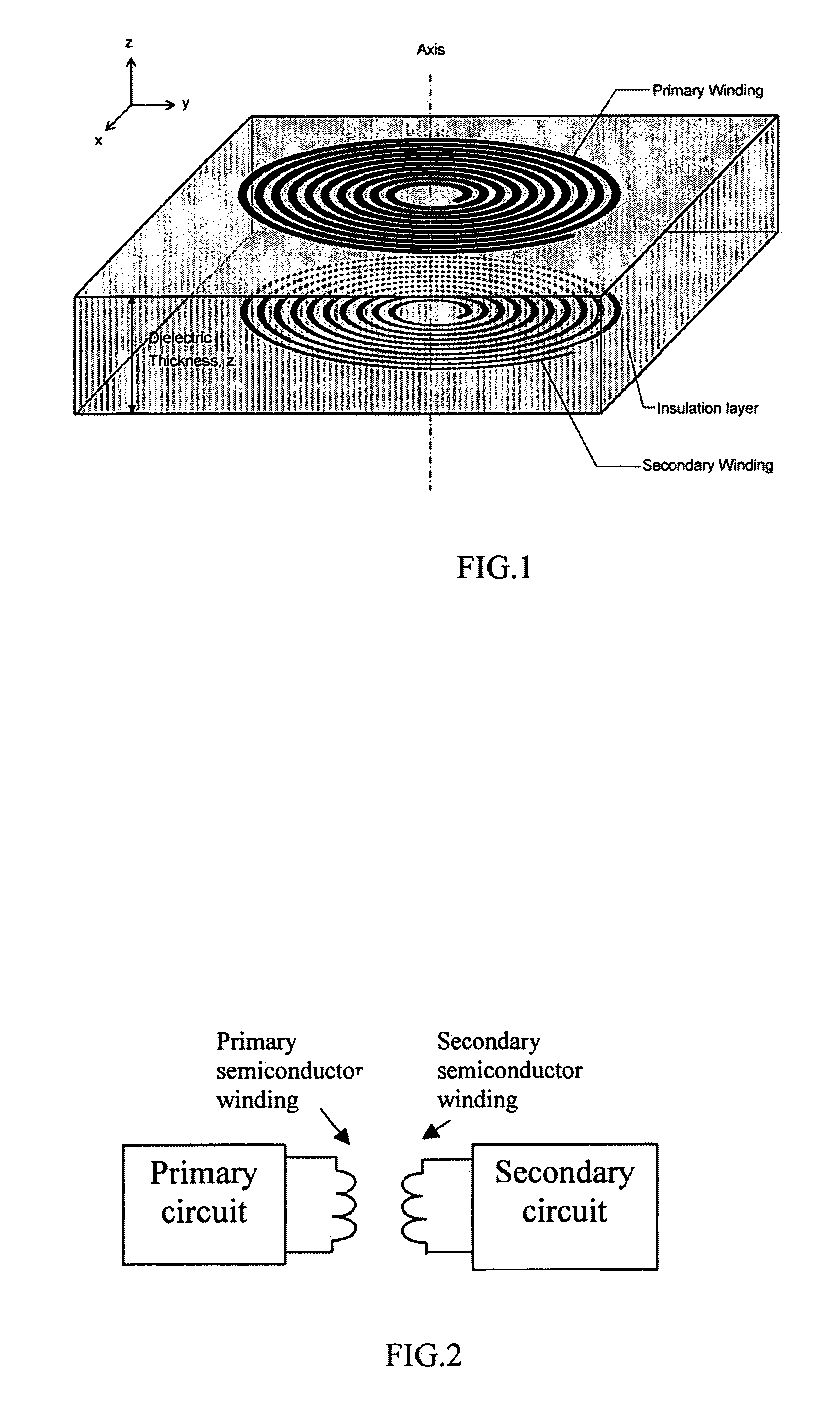
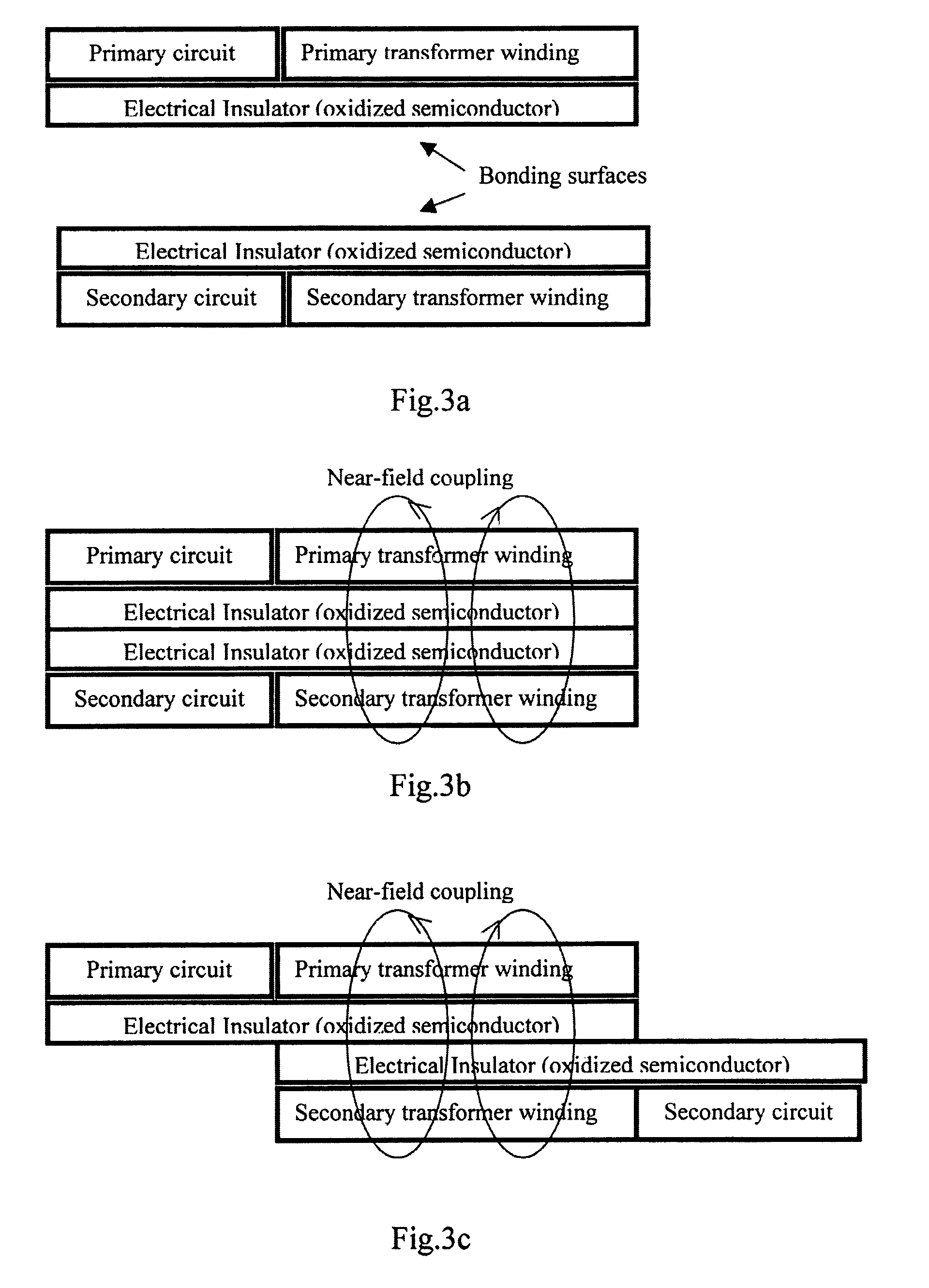
[0020]In existing electronic circuits, magnetic transformers with magnetic cores are usually used as separate components in a circuit board. Despite the recent development of integrated magnetics, these magnetic components are still treated as individual (or discrete) components in circuit constructions and cannot be integrated into semiconductor integrated electronic circuits. As will be seen from the following description of preferred embodiments of the invention, this invention is concerned with a “semiconductor transformer” concept in which all (or at least substantially all) parts of the transformer are made of semiconductor materials and can therefore be fully incorporated into integrated semiconductor electronic circuits (more simply called integrated circuits).

[0021]In preferred embodiments of the present invention the windings are made of highly doped semiconductor paths. This proposal changes the conventional concept of “magnetic” transformers to “semiconductor” transforme...


PUM


Abstract

A planar transformer structure, which can be constructed in an integrated semiconductor circuit without using traditional metallic windings. To avoid large thermal expansion of metallic spiral windings and associated mechanical stress on a metal-semiconductor interface, it is suggested that highly doped semiconductor materials with or without silicides and salicides can be used to form windings or conducting paths because their thermal expansion coefficients are similar to that of semiconductor material. The planar semiconductor transformer may find application for low-power and signal transfer that needs electrical isolation.

Description

FIELD OF THE INVENTION[0001]This invention relates to novel transformer structures, and in particular to transformers formed of semiconductor materials.BACKGROUND OF THE INVENTION[0002]Traditional transformers are “electromagnetic devices” because each of them consists of a magnetic core and copper windings and so the structure of the core is magnetic in nature. In general, transformers are located in circuit boards as separate components and cannot be integrated into semiconductor based integrated circuits. The recent development of coreless planar transformers [see references 1-6] and their operating principles has opened a door to the construction of non-magnetic coreless planar transformers and such coreless planar transformers have been implemented into printed-circuit-boards (PCBs) for a range of power and signal transfer applications [see references 7-11].PRIOR ART[0003]An industrial adoption of a coreless planar transformer gate-drive concept has been demonstrated by Infineo...

Claims


Application Information

Patent Timeline
Patent Type & Authority Patents(United States)
IPC IPC(8): H01L29/00
CPCH01F19/00H01F27/2804H01L27/0688H01F2017/0086H01F2027/2819
Inventor HUI, SHU YUEN RON
Owner CITY UNIVERSITY OF HONG KONG
Learn More