
Line voltage interface for automation systems

a technology of automation system and line voltage, applied in the field of automation system, can solve the problems of inability to transfer the full motor load, the volume of components required, and the inability to mount equipment in tight or compact spaces, and achieve the effect of convenient mounting of multiple units, convenient installation and operation, and convenient mounting

Inactive Publication Date: 2011-11-01
AGROLINKS
View PDF4 Cites 0 Cited by
  • Summary
  • Abstract
  • Description
  • Claims
  • Application Information

AI Technical Summary

Benefits of technology

"The present invention is about a device that acts as a junction between an automation controller, a power source, and a multifunction load. It includes terminal blocks with terminals, function input terminals, alternative load terminals, a power path circuit, and a control circuit. The device also has indicator lights and a three way mode selection switch that allows the user to control the power path between the power source and the load terminals. The device is compact, easy to install and operate, and can be used in multiple situations over time. The technical effects of this invention are improved installation and versatility of the device."

Problems solved by technology

These existing low voltage pilot relays or interface devices may or may not have integral override switches, but are not capable of transferring the full motor load.
The sheer volume of components required often necessitates that large or multiple electrical boxes be utilized.
Such a bulky arrangement can prohibit mounting of the equipment in tight or compact spaces.
The complicated and non-compact manner in which present art relay / switch systems are built for automation interfacing inhibits the ability to locate components and wiring in the most cost-effective, compact, and desirable configuration.

Method used


Image

  • Line voltage interface for automation systems
  • Line voltage interface for automation systems
  • Line voltage interface for automation systems

Examples


Embodiment Construction

[0013]Embodiments of the present inventive concept are drawn to an integrated interface for use in automation control applications replacing separate relays, switches and their associated wiring with a compact integrated device that is easy to install.

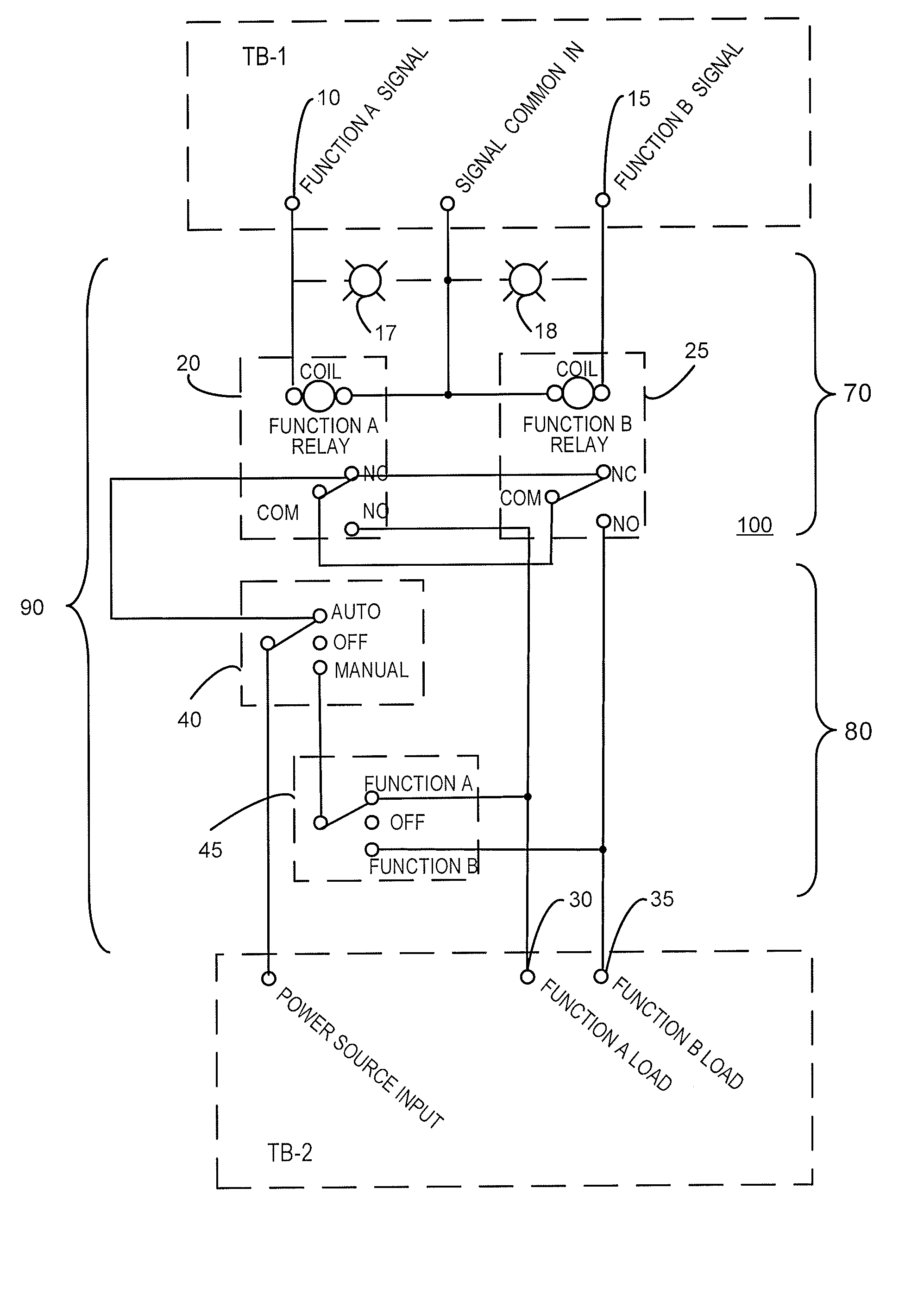
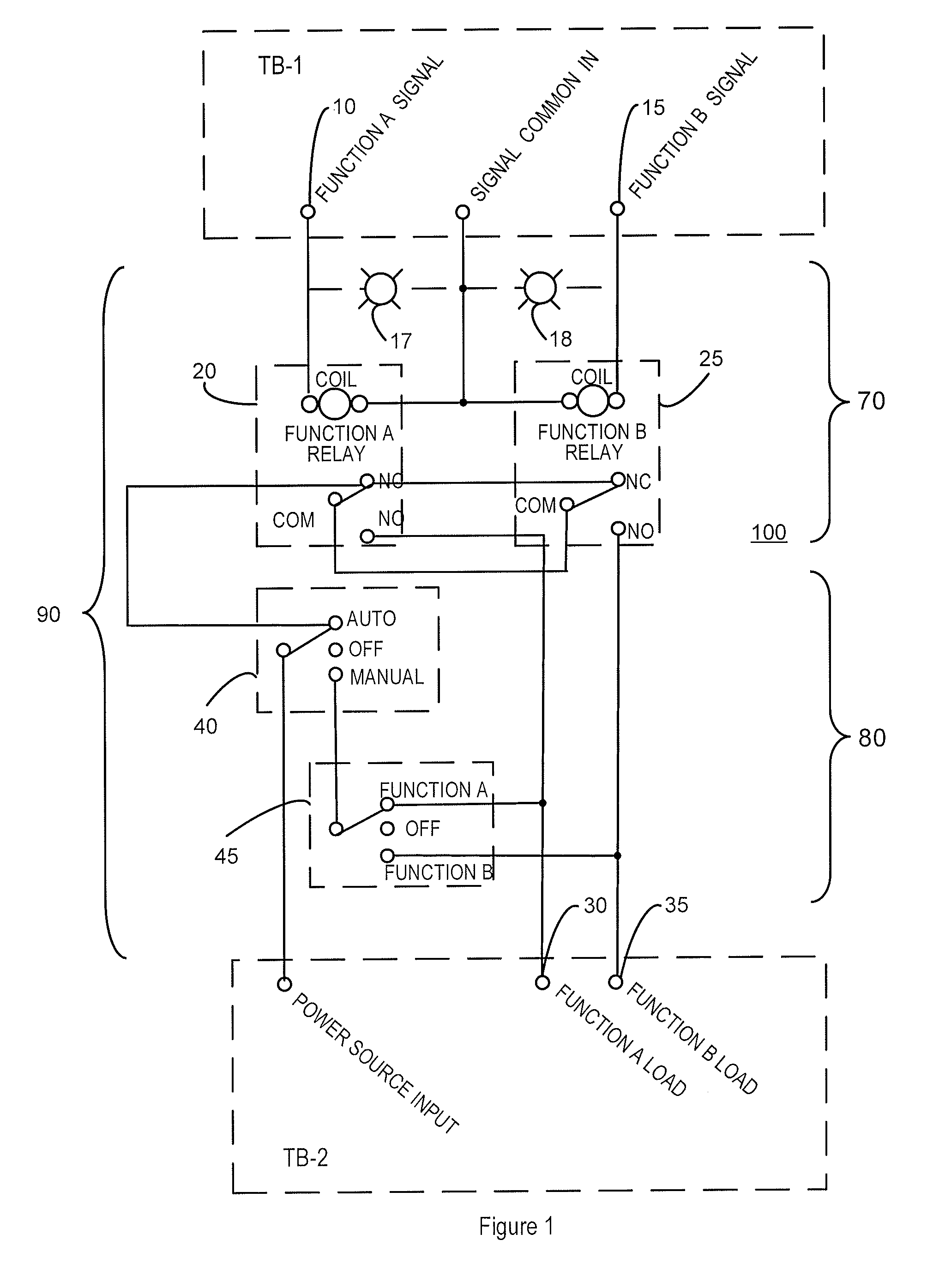
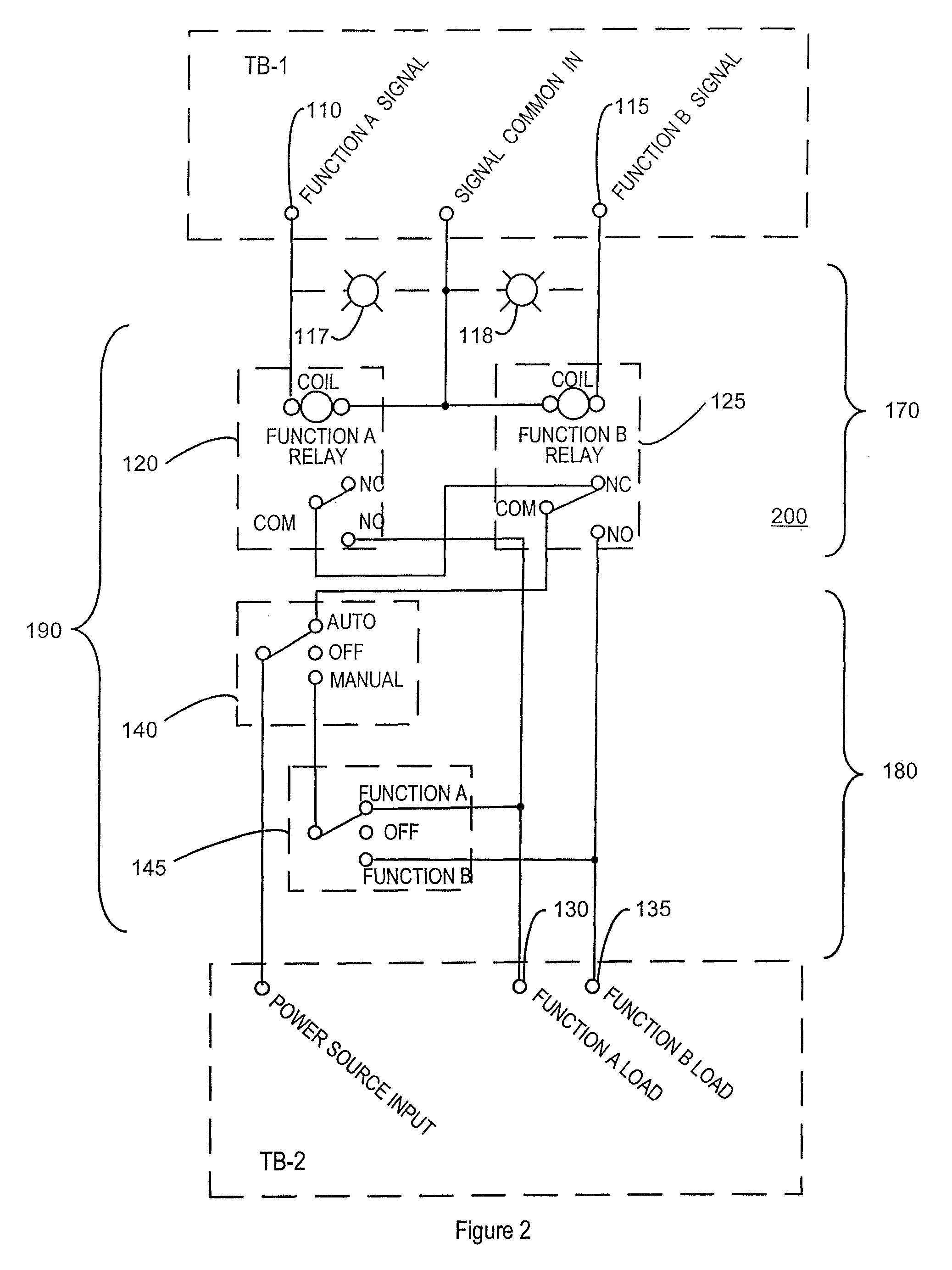
[0014]FIG. 1 illustrates interconnected circuits, interface 100, interrelating an automation controller unit, a power source, and two functional loads. Power controller 90 of interface 100 comprises control circuit 70 and power path circuit 80. Control circuit 70 receives function A and B signals at function input terminals 10 and 15 from an automation controller unit (not shown) and controls power path circuit 80 by means of relays 20 and 25. Power path circuit 80 selectably connects the power source input terminal to load terminals 20 and 25. Signals A and B correspond to the two functions of a dual function load; for instance, the low speed and high speed of a two-speed motor, which may effect such operations as the cooling stages o...


PUM


Abstract

An integrated printed circuit board-based solid state line voltage interface for use in automation control system applications. Relays connect various functional loads to the line level source in response to input from a controller unit. Switches enable a user to override the controller and manually control the connection of the functional loads. An alternative embodiment further includes limit switches and time delays. The compact nature of the device facilitates ease of installation, mounting of multiple units in less space, and mounting in various specialized location as desired.

Description

PRIORITY CLAIM[0001]This application is a continuation in part of application Ser. No. 12 / 122,464, entitled “Line Voltage Interface for Automation Systems” filed on May 16, 2008 now abandoned, and claims priority thereto.TECHNICAL FIELD[0002]The present invention relates to the field of automation systems. More specifically, the invention relates to the interface between automation control units, power sources, and multifunction loads, such as, for instance, variable speed and / or reversible motors.BACKGROUND ART[0003]Automation systems employ controller devices such as microprocessors, computers, and programmable logic controllers (PLC's), to control machinery, equipment, and processes. These systems may control various equipment including fans, dampers, valves, vents, shades, and other equipment. Often, automation controller units read a set of digital and / or analog inputs, apply a set of logic statements, and in response generate a set of low or very low voltage analog and / or digi...

Claims


Application Information

Patent Timeline
Patent Type & Authority Patents(United States)
IPC IPC(8): H02P7/00
CPCG05B19/042G05B2219/21014G05B2219/25451
Inventor BROOKS, PAUL
Owner AGROLINKS
Learn More