Press machine controller

a technology for press machines and controllers, applied in the direction of programme control, forging hammers, and machines with progressive movements, etc., can solve the problems of large torque required to restart the press machine, static friction acting on the link mechanism, and failure to work with the inner for

Active Publication Date: 2011-11-01
FANUC LTD
View PDF13 Cites 26 Cited by
  • Summary
  • Abstract
  • Description
  • Claims
  • Application Information

AI Technical Summary

Benefits of technology

[0010]This invention has been achieved in view of this situation, and the object thereof is to provide a press machine controller whereby the press machine, even if stopped with the slide located at the bottom dead center, can be restarted with a small torque.

Problems solved by technology

However, in the case where the press machine is stopped with the slide located at the bottom dead center for the purpose of confirming the operation of the press machine or otherwise, the inertial force fails to work and the static friction acts on the link mechanism, etc.
Therefore, a large torque is required to restart the press machine.
However, a large servo motor is expensive, resulting in increased production cost of the press machine.

Method used


Image

  • Press machine controller
  • Press machine controller
  • Press machine controller

Examples


first embodiment

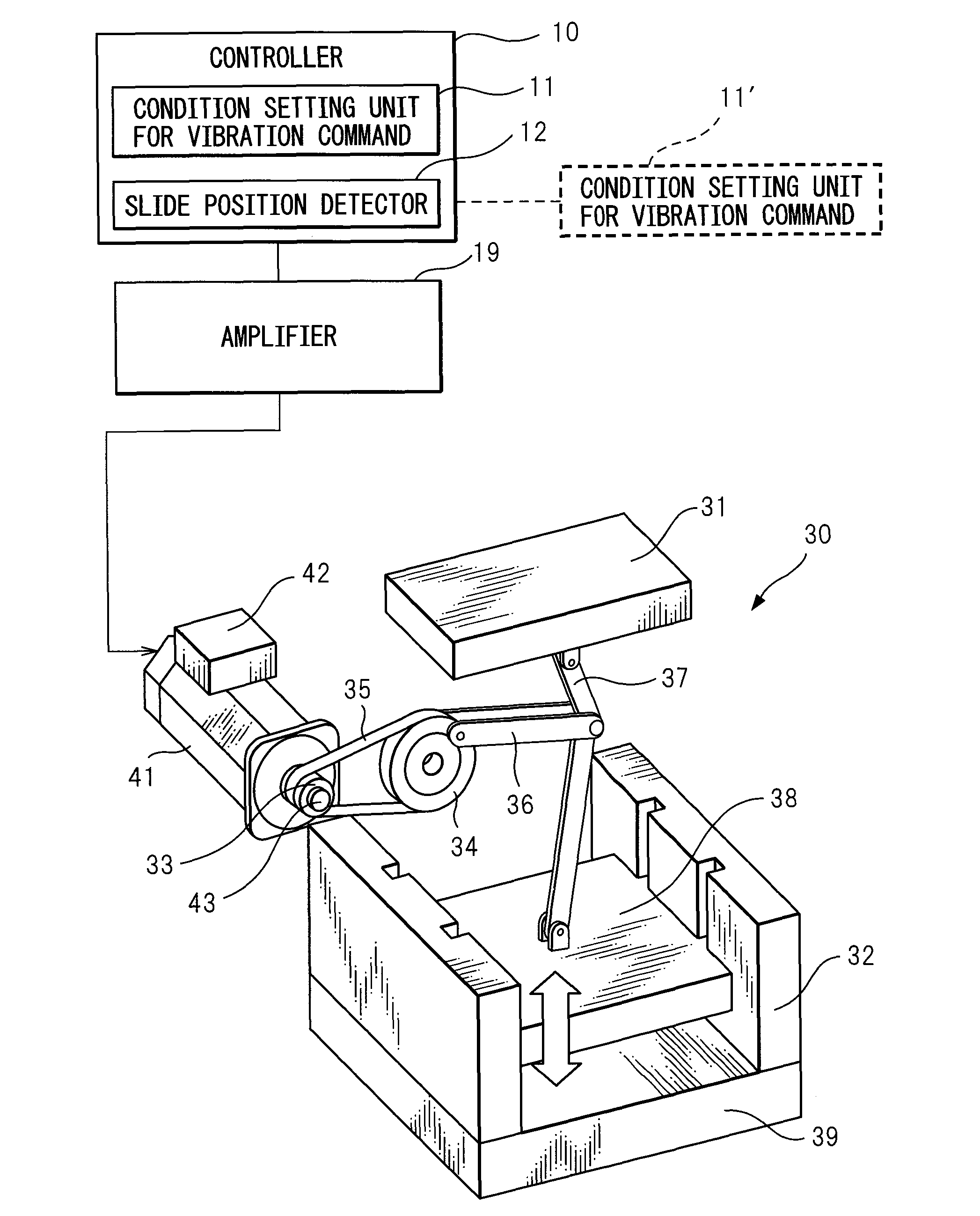
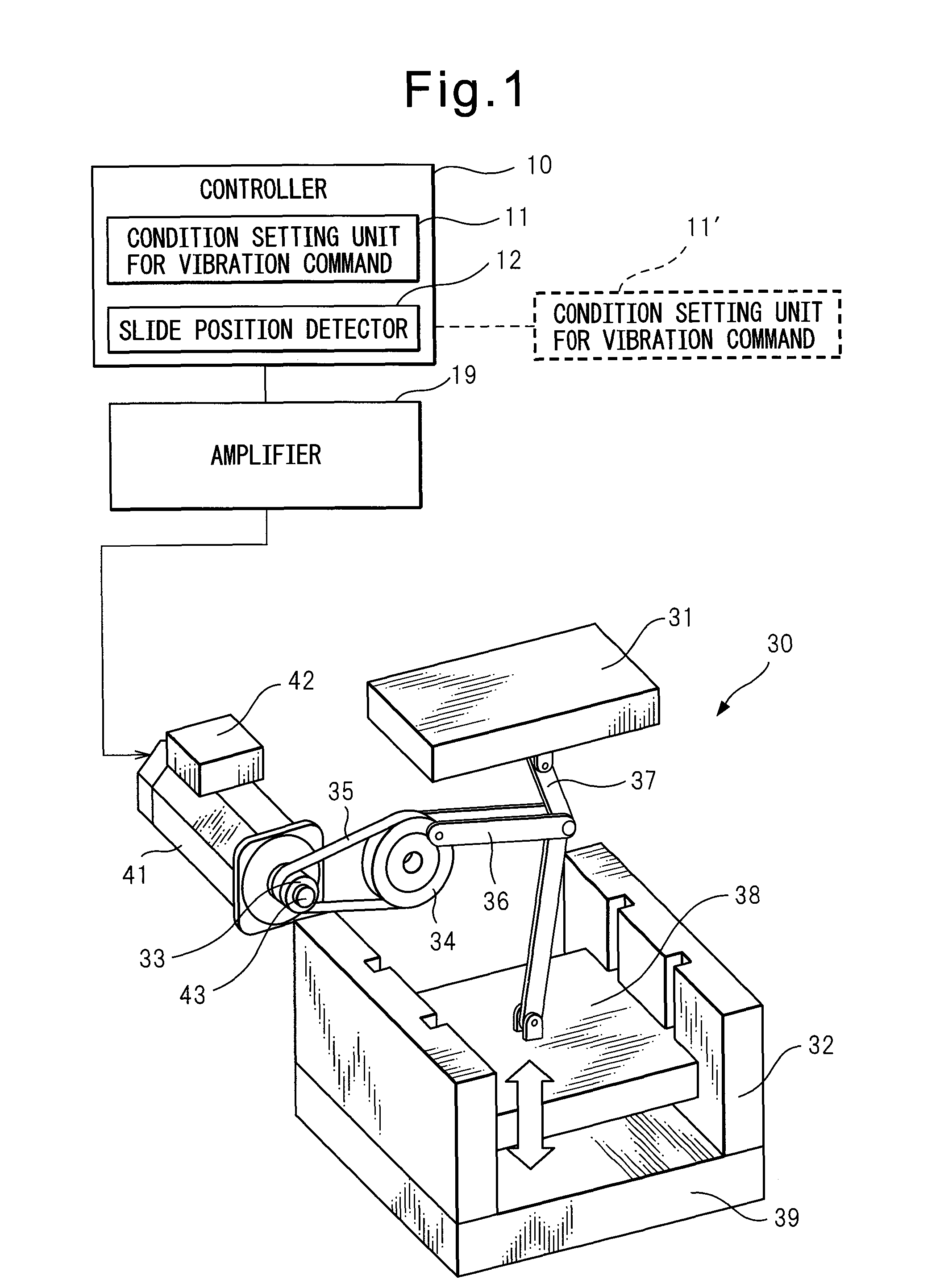
[0033]FIG. 3 is a block diagram showing the press machine controller according to the invention. As shown in FIG. 3, the position command CP is read from the machining program for each control period and reduced by the position fed back from the position detector 42 thereby to generate a position deviation. The position deviation is multiplied by a position gain in a position gain multiplier 15 thereby to generate a speed command CV.

[0034]Then, the speed feedback data generated based on the change in the position feedback data, within a predetermined time, detected by the position detector 42 is subtracted from the speed command CV thereby to calculate a speed deviation. This speed deviation is input to a speed control portion 16. The speed control portion 16 outputs a torque command CT (current command) based on the speed deviation. In FIG. 3, a section for outputting at least one of the position command CP, the speed command CV and the torque command CT is designated as a command ...

second embodiment

[0050]FIG. 8 is a block diagram showing a press machine controller according to the invention. As shown in FIG. 8, the device according to this embodiment includes, as the members related to the first servo motor 41a, a position gain multiplier 15a, a speed control portion 16a, an amplifier 19a and first vibration command adding portions 21a, 22a, 23a which form a command generator 20a. Similarly, the members related to the second servo motor 41b include a position gain multiplier 15b, a speed control portion 16b, an amplifier 19b and second vibration command adding portions 21b, 22b, 23b which form a command generator 20b. Incidentally, as can be seen from FIG. 8, a vibration command generator 13 is shared by the command generators 20a, 20b.

[0051]In the second embodiment, a similar process to the process described with reference to FIG. 4, etc., is executed. According to the second embodiment, in the case where the vibration command T is added to the torque command CT (see step 10...


PUM

PropertyMeasurementUnit
reduction ratioaaaaaaaaaa
speedaaaaaaaaaa
torqueaaaaaaaaaa

Abstract

A press machine controller (10) for controlling a press machine (30) having a servo motor (41) to drive a slide (38) via a reduction mechanism (37) changed in reduction ratio in accordance with the position of the slide (38) is disclosed. The device includes a command generator (20) for generating at least one of a position command, a speed command and a torque command for the servo motor (41); a vibration command generator (13) for generating a vibration command based on a parameter preset for the press machine controller (10); a slide position detector (12) for detecting the position of the slide (38); and a vibration command adding portion (21, 22, 23) for adding the vibration command to any one of the position command, the speed command and the torque command for the servo motor (41) in the case where the slide position is in a predetermined range. The press machine, even if stopped with the slide at the bottom dead center, can be restarted with a small torque.

Description

RELATED APPLICATIONS[0001]The present application is based on, and claims priority from, Japanese Application Number 2009-161086, filed Jul. 7, 2009, the disclosure of which is hereby incorporated by reference herein in its entirety.BACKGROUND OF THE INVENTION[0002]1. Field of the Invention[0003]This invention relates to a press machine controller for controlling a press machine including a servo motor which drives a slide via a reduction mechanism with the reduction ratio changed in accordance with the position of the slide.[0004]2. Description of the Related Art[0005]Conventionally, a mechanical press in which press forming time can be shortened by operating a slide at high speed can be used as a press machine. Japanese Unexamined Patent Publication No. 10-249590 discloses a mechanical press having a link mechanism. The slide of the press machine disclosed in Japanese Unexamined Patent Publication No. 10-249590 moves up and down with the motion of a servo motor transmitted through...

Claims


Application Information

Patent Timeline
Patent Type & Authority Patents(United States)
IPC IPC(8): G05B1/06
CPCB30B1/14B30B15/26B30B15/14
Inventor OKITA, TADASHIKAWAMURA, HIROYUKIKAMETA, KOUKI
Owner FANUC LTD
Why Eureka
Try Eureka