Cable, cord, hose, and rope holding device

Inactive Publication Date: 2011-11-08
DELLINGER LOY
View PDF21 Cites 31 Cited by
  • Summary
  • Abstract
  • Description
  • Claims
  • Application Information

AI Technical Summary

Benefits of technology

[0010]The body comprises a framework, a plurality of rods that is attached to the framework by any conventional means and that rotates relative to the framework, and a plate that is connected to the framework. The plate has least one aperture that is used to connect the body to the arm. The framework carries the rods and forms a perimeter around the rods. Two or more rods are in parallel and are disposed in a first plane. At least one rod is disposed in a second plane that is not parallel to the first plane. The configuration of the rods allows for cables to be secured by at least one rod without interference from any of the other rods. The rods and the framework communicate to releasably secure the cable in a fixed position within the device. In particular, by weaving the cable through the rods, static friction maintains the cable in a fixed position within the body. However, the static friction may be overcome by manually pulling the cable and the cable can be pulled in any direction.
[0011]The arm comprises a first end and a second end. Each end of the arm has at le

Problems solved by technology

One disadvantage of this previously known practice of allowing cables, cords, hoses, and ropes to hang over a roof is that the cable, cord, hose, or rope can become damaged.
If fiber optic cables are damaged, this could lead to a decrease or total cessation of signals traveling through the cable.
Damaged electrical cables and electrical cords can lead to loss of power supply to electrical equipment and can also lead to accidental electrocution due to exposed surfaces of the electrical cables and cords.
Additionally, damaged water hoses can lead to water leakage on the roof, increasing the potential for slips and falls as well as increasing the possibility of accidental electrocution.
Dam

Method used


Image

  • Cable, cord, hose, and rope holding device
  • Cable, cord, hose, and rope holding device
  • Cable, cord, hose, and rope holding device

Examples


Embodiment Construction

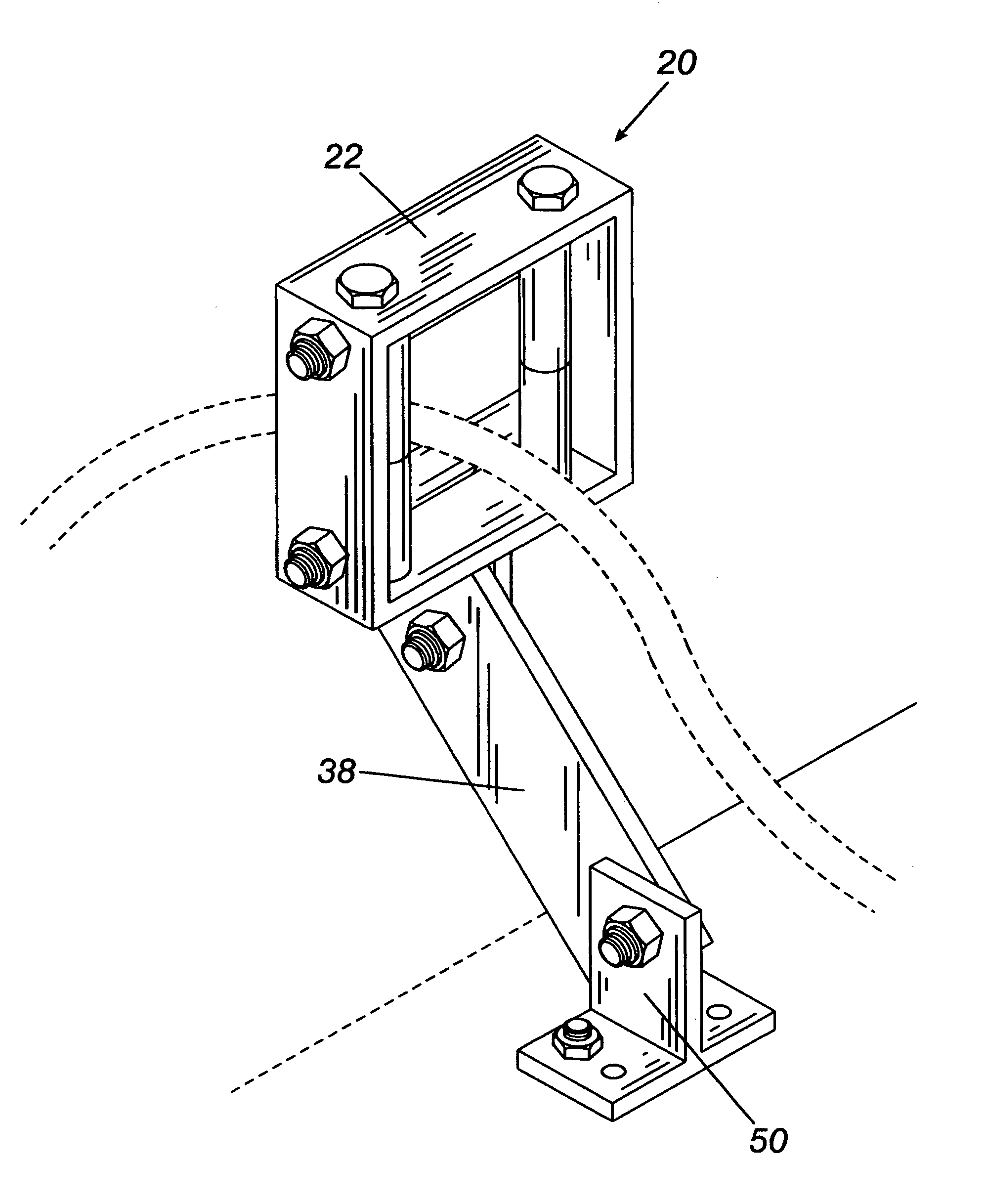
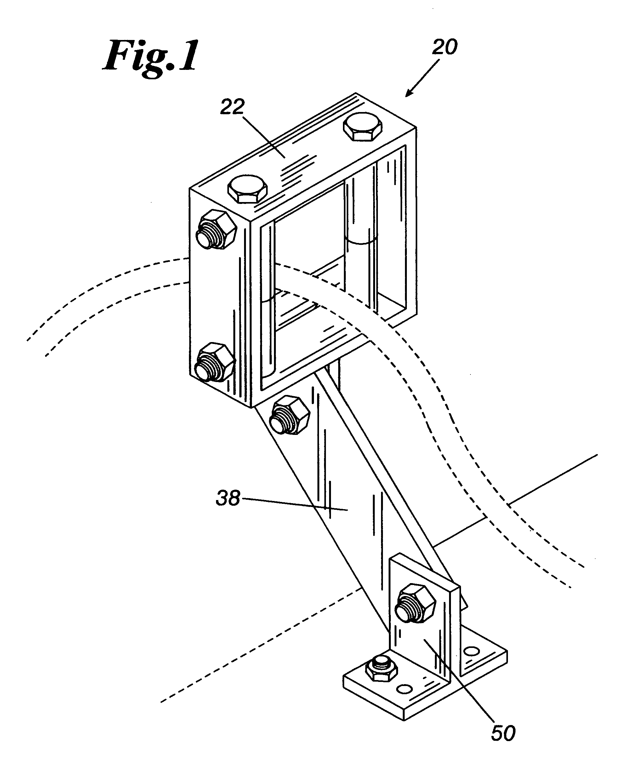
[0024]Referring now to the drawings and particularly to FIG. 1, the invention is a cable holding device 20 for holding cables when work is performed on roof tops. As used herein, the term cable is to be broadly construed and is inclusive of cables, cords, hoses, ropes, wires, and similar items. The present invention 20 holds cables and allows cables to drape over the edge of a building without touching the terminal edge of the roof.

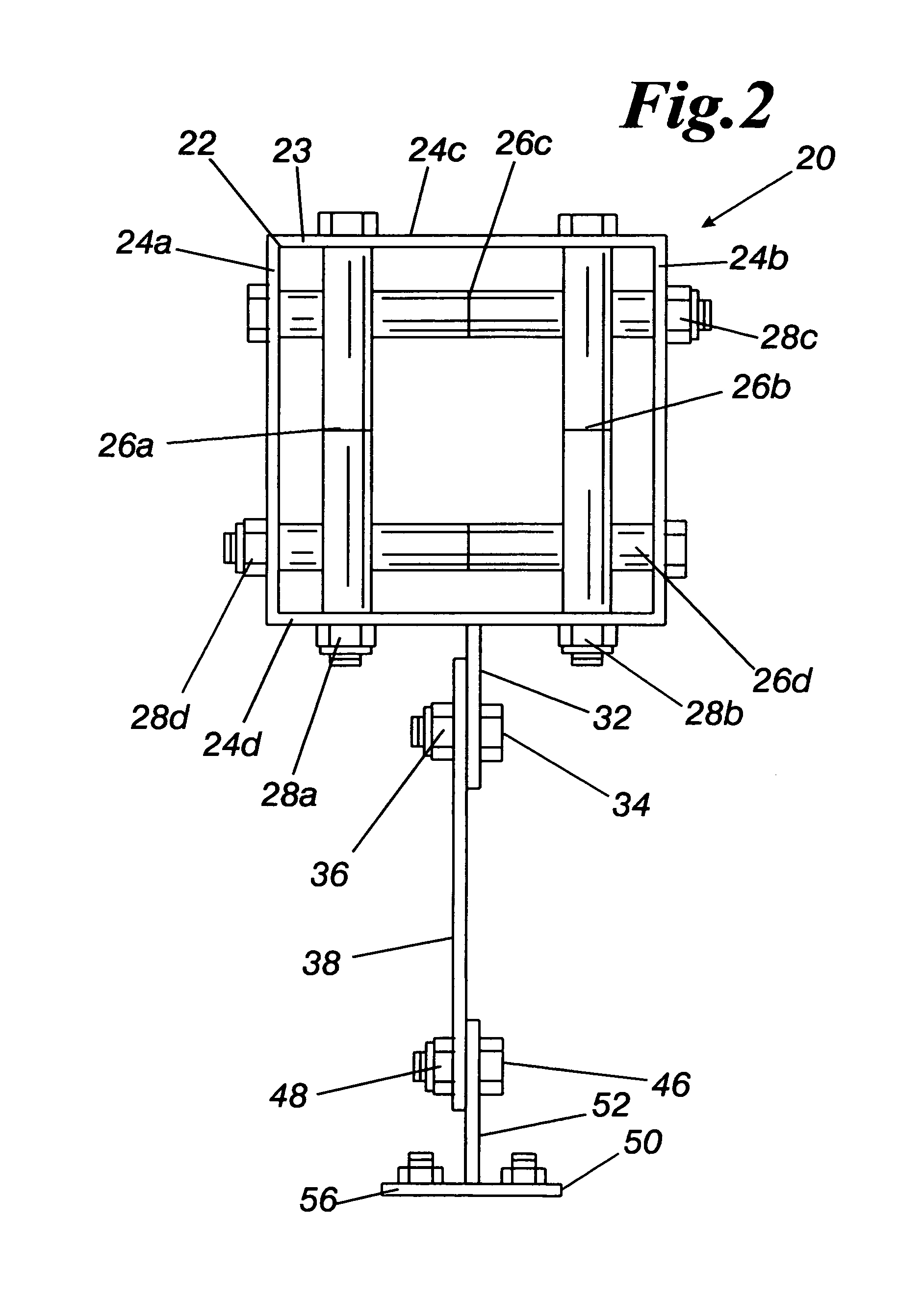
[0025]The cable holding device 20 is comprised of a body 22 for holding the cables, a mounting bracket 50 for mounting the invention to a roof, and an arm 38 that serves to extend the body 22 beyond the terminal edge of a roof. The body 22 and the mounting bracket 50 are respectively attached to the arm 38 by any conventional means. The mounting bracket 50 cooperates with the arm 38 to extend the body 22 a suitable distance beyond the terminal edge of a roof top, allowing cables held within the body 22 to drape over the edge of a building without touching...


PUM


Abstract

The present invention is a device that can be used to hold cables, cords, hoses, ropes, and similar objects that are used during work on a roof top. The cable holding device is comprised of a body for holding the cables, a mounting bracket for mounting the invention to a roof, and an arm that serves to extend the body beyond the terminal edge of a roof. The body and the mounting bracket are respectively attached to the arm by any conventional means. The mounting bracket cooperates with the arm to extend the body a suitable distance beyond the terminal edge of a roof top, allowing cables held within the body to drape over the edge of a building without touching the terminal edge of the roof.

Description

BACKGROUND OF INVENTION[0001]1. Field of Invention[0002]This invention relates to a device that can be utilized to hold cables, cords, hoses, and ropes when work is performed on roof tops. The invention prevents cables, cords, hoses, ropes, and similar objects from getting caught on the edge of a roof, eave of a roof, stud wall, concrete wall, or similar structure.[0003]2. Description of Prior Art[0004]Cables, cords, hoses, and ropes may be required during work on a roof top. While the work is being performed, cords from electrical equipment are often left hanging over the side of a roof top to allow the free ends to be plugged into electrical sockets at ground level. Hoses are also often left hanging over the side of a roof top to connect to a water receptacle, air compressor, or other receptacle at ground level. Similarly, electric cables, fiber optic cables, and ropes may also hang over the side of a roof during roof top work.[0005]One disadvantage of this previously known practi...

Claims


Application Information

Patent Timeline
IPC IPC(8): F16L3/00
CPCE04D15/00F16L3/1218F16L3/22F16L3/24H02G1/06F16L3/243
Inventor KOWALESKI, KERRY KEITH
Owner DELLINGER LOY
Why Eureka
Try Eureka