Wheel for a vehicle

a technology for wheels and vehicles, applied in the direction of spoked wheels, transportation and packaging, rolling resistance optimization, etc., can solve the problems of increasing the mass and moment of inertia of wheels, and the use of composite materials, so as to improve torque transmission, increase static friction between the at least one first and the at least one second contact area, and good results

Active Publication Date: 2019-02-28
MUBEA CARBO TECH GMBH
View PDF0 Cites 3 Cited by
  • Summary
  • Abstract
  • Description
  • Claims
  • Application Information

AI Technical Summary

Benefits of technology

[0038]Good results may be achieved if connection elements, such as e.g. screws or bolts, are aligned essentially perpendicular to the intermediate layer. Hence static friction between the at least one first and the at least one second contact area can be increased which allows improving torque transmission between a wheel center and a rim.
[0039]Alternatively or in addition, an adhesive may be inserted in the junction region between the wheel center and the rim in order to at least improve sealing of this region. Thus, intrusion of moisture into the space between connection element, rim and bushing (of present) and / or leakage of pressurized gas from the tire / rim volume can be decreased. The connection element may be at least partially embedded in such an adhesive. Good results may be obtained if the wheel comprises a bushing and the adhesive is inserted in said junction region before the bushing and the connection element are mounted. Good results can be obtained if polyurethane adhesives are used.
[0040]At least a part of the rim's surface which is directed to the wheel and during operation exposed to the pressurized gas in the tire may be coated with a barrier layer that is impermeable to the gas to be filled in the tire / rim-volume, in particular with a layer made from a polymeric substance. Thus, stress corrosion cracking and leakage of pressurized gas through micro-cracks may be reduced. Good results may be obtained if the barrier layer comprises a material that has a higher elasticity (elastic modulus) than the matrix of the fiber reinforced plastic, e.g. a silicone material, in particular a silicone varnish. Using a material with a relatively high elasticity allows reliable sealing of micro-cracks (or even larger cracks) that open due to cyclic loading or changes in wheel temperature. For some applications, the barrier layer may comprise multiple layers made from the same and / or from different materials. In one embodiment, the barrier layer comprises a layer that increases friction of the tire mounted on the rim. Hence relative movements between the tire and the rim can be prevented.

Problems solved by technology

Furthermore, the two part wheel does enable certain designs of the wheel center that cannot be realized with wheels made in one part.
The usage of composite materials may decrease the mass and moment of inertia of wheels even more if compared to designs using metals only.

Method used


Image

  • Wheel for a vehicle
  • Wheel for a vehicle
  • Wheel for a vehicle

Examples


Embodiment Construction

[0056]The foregoing summary, as well as the following detailed description of the preferred embodiments, is better understood when read in conjunction with the appended drawings. For the purpose of illustrating the invention, an embodiment that is presently preferred, in which like numerals represent similar parts throughout the several views of the drawings, it being understood, however, that the invention is not limited to the specific methods and instrumentalities disclosed.

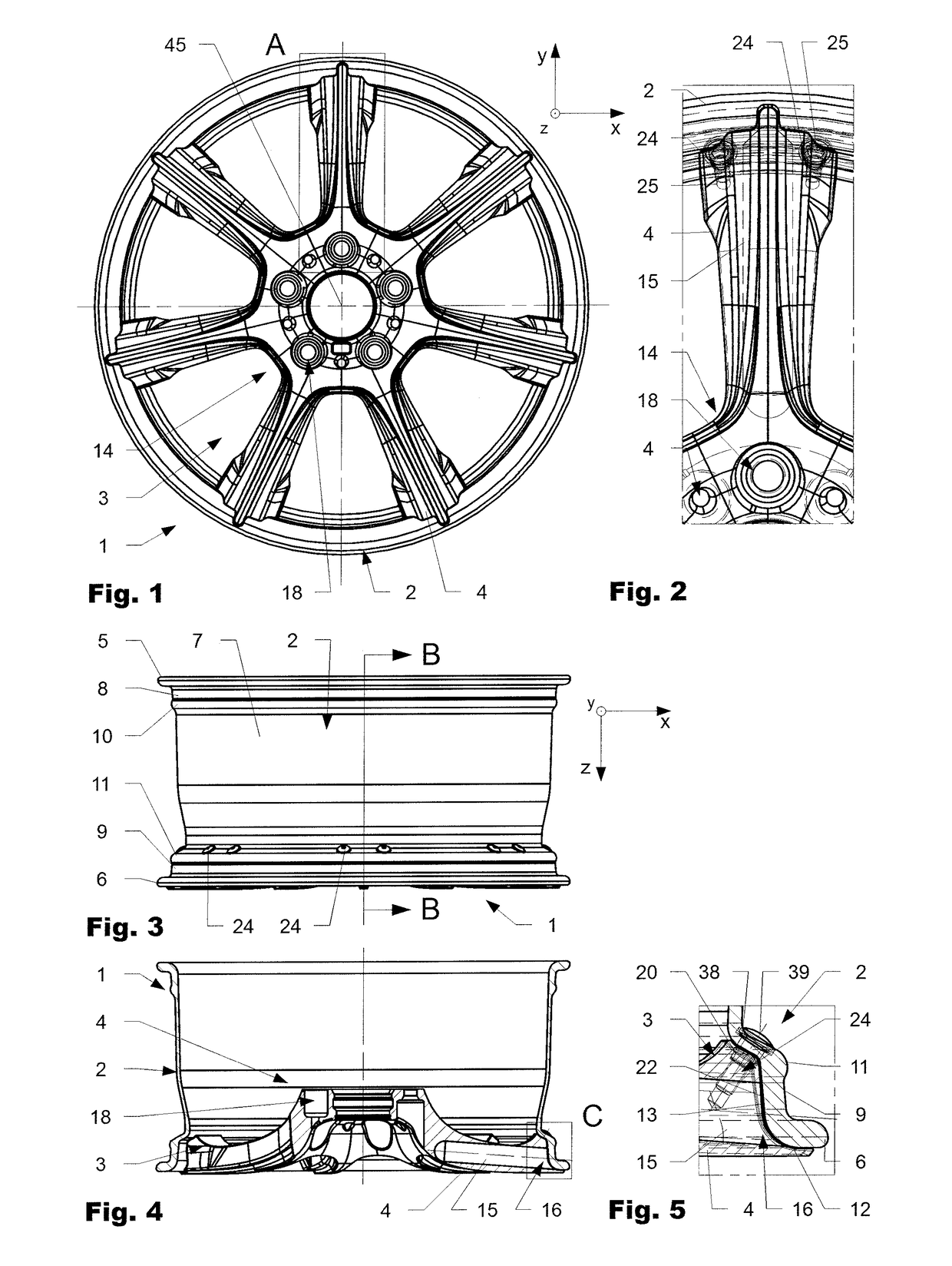
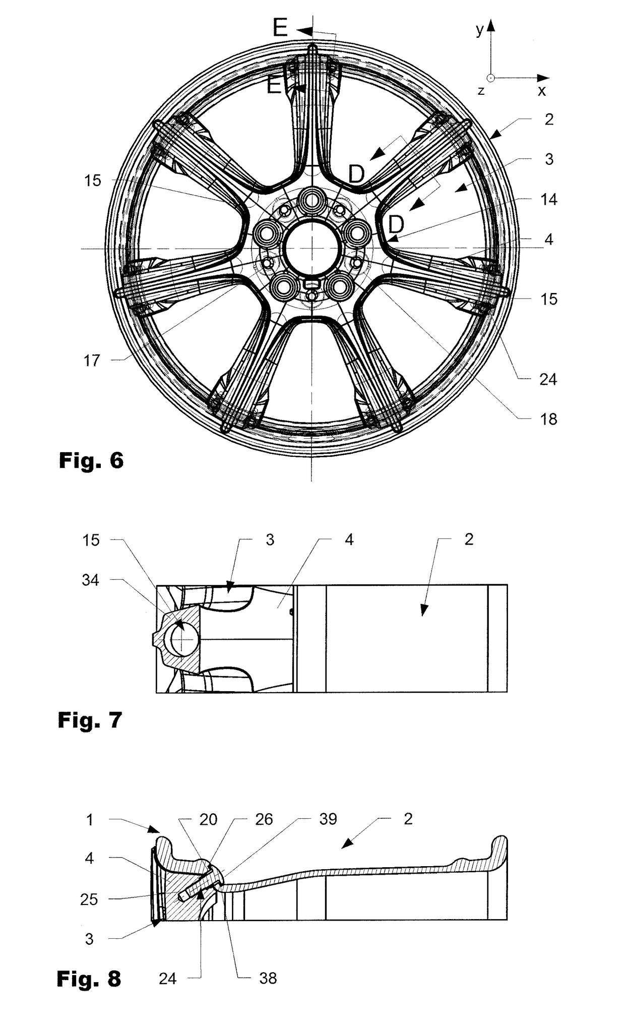
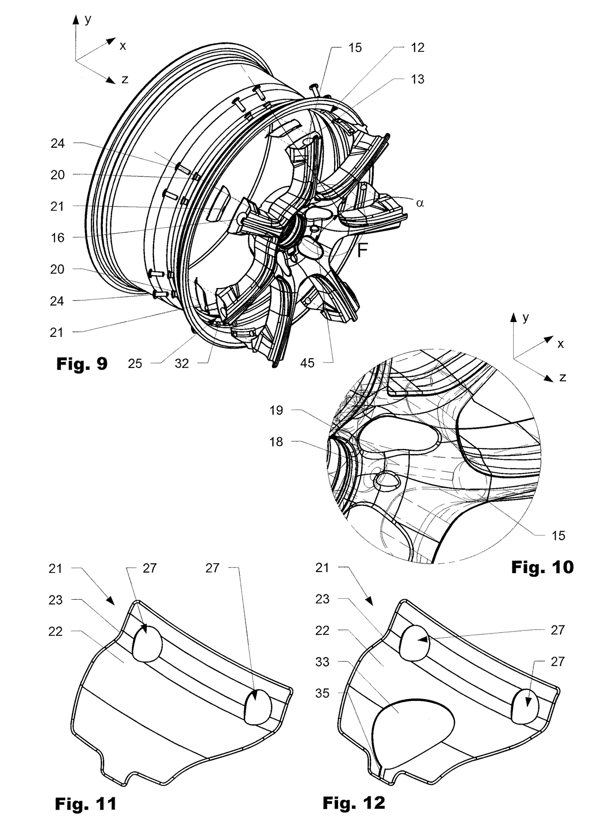
[0057]FIGS. 1-9 show several variations of a wheel 1 according to the invention. The wheel 1 comprises a rim 2 made from a fiber reinforced plastic, such as a carbon fiber reinforced plastic. In addition, the rim 2 comprises a rim well 7 which is arranged between an inner rim edge 5 and an outer rim edge 6, suited to receive a tire (not shown). The wheel 1 further comprises a wheel center 3 that comprises a wheel hub 14 which can be connected to a vehicle's wheel suspension (not shown) and a serves as a suppor...


PUM

PropertyMeasurementUnit
thicknessaaaaaaaaaa
contact areaaaaaaaaaaa
bearing areaaaaaaaaaaa

Abstract

A storage device for an extractable hose arranged in an installation space. The storage device includes a first housing member defining a first storage compartment. The first storage compartment is configured to house at least a portion of the hose which is extractable from the first storage compartment via a hose port arranged at the first housing member. The first housing member includes at least one spatial curved wall section eluding the contour of at least one module extending into the installation space.

Description

BACKGROUND OF THE INVENTIONField of the Invention[0001]The present invention is directed to a wheel for a vehicle comprising a rim made of composite material and a wheel center made out of the same or a different material, such as a light weight metal alloy.Discussion of Related Art[0002]Light vehicle wheels are desirable to improve the driving quality and performance as well as to keep the overall vehicle weight light. At the same time, safety regulations exists to ensure sufficient durability, especially of the wheel's rim. On the one hand, the design aims to make the wheel as light as possible, on the other hand, it is necessary to provide a sufficient durable and strong mechanical structure. The wheels generally feature air openings and spokes which extend radially from the rim spider to the rim well of the wheel.[0003]Due to advances in material research, the wheel material is further shifted to light-metal and composite materials, which are light, durable and able to bear high...

Claims


Application Information

Patent Timeline
Patent Type & Authority Applications(United States)
IPC IPC(8): B60B5/02B60B1/14B60B21/06B60B21/12B60B23/06B60B3/04B60B3/10
CPCB60B5/02B60B1/14B60B21/068B60B21/12B60B23/06B60B3/044B60B3/10B60B2310/305B60B2360/341B60B2900/111B60B2900/311Y02T10/86B60B23/08
Inventor RENNER, CHRISTOPH
Owner MUBEA CARBO TECH GMBH
Why Eureka
Try Eureka