
Liquid-cooled mold for the continuous casting of metals

a technology of liquid-cooled molds and metals, which is applied in the field of liquid-cooled molds for the continuous casting of metals, can solve the problems of failure of welding connection, and even cracks in the mold plate, so as to reduce the static friction between the supporting plate and the mold plate, and uniform expansion of the mold plate

Inactive Publication Date: 2005-03-08
KME GERMANY GMBH & CO KG
View PDF6 Cites 2 Cited by
  • Summary
  • Abstract
  • Description
  • Claims
  • Application Information

AI Technical Summary

Benefits of technology

The present invention is based on improving a liquid-cooled mold for the continuous casting of metals to the effect that the static friction between the supporting plate and the mold plate is reduced, and an uniform expansion of the mold plate compared to the supporting plate is made possible.
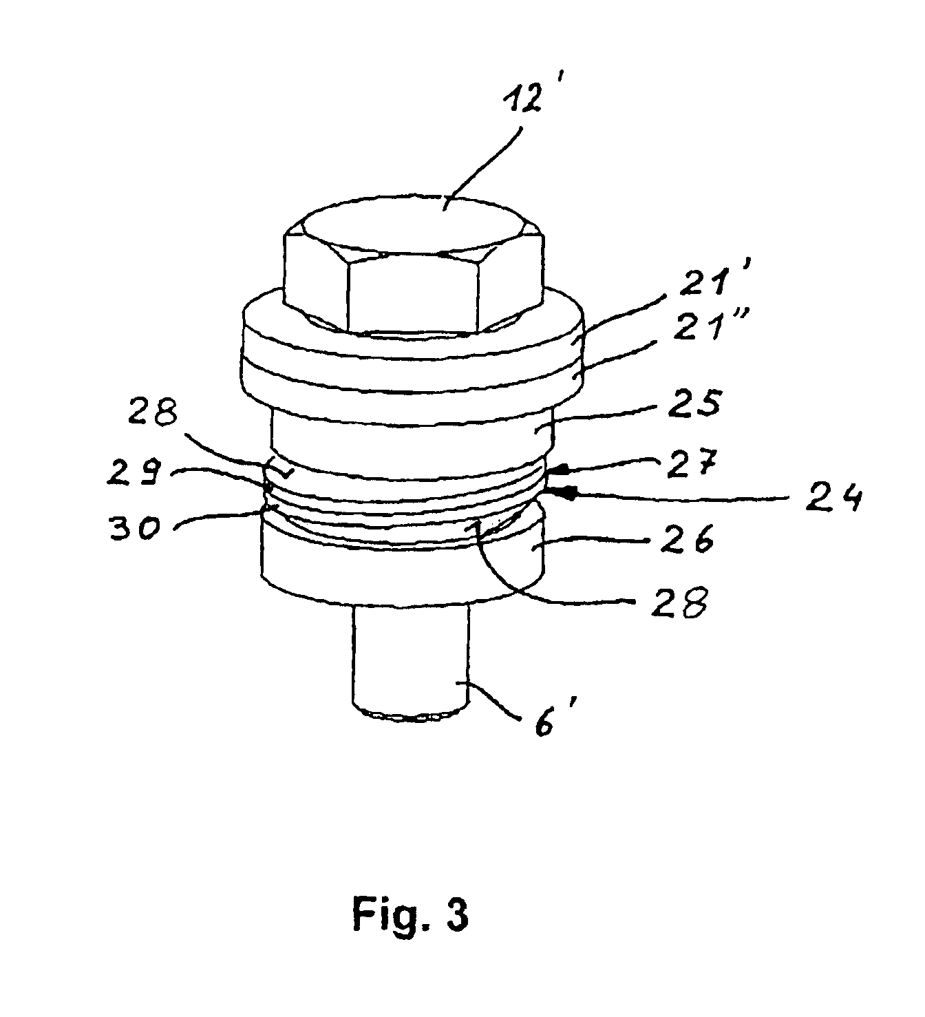
Articulated systems in the sense of the present invention are supports which allow a lateral movement of the bolt in a through-hole of the supporting plate that is made larger than the bolt diameter, and thereby admit an essentially parallel relative motion between the mold plate and the supporting plate. A sliding element in the sense of the present invention is any element that is suitable for reducing the static friction and / or the sliding friction between the sliding surfaces.
It is possible to develop the sliding element as a sliding coating, which is assigned to at least one of the sliding surfaces in an undetachable manner. That means that only one of the sliding surfaces or perhaps both sliding surfaces may be provided with a sliding coating. The sliding coating is suitable for reducing the coefficient of static friction and / or the coefficient of sliding friction between the articulation members, and thereby making simpler a relative motion of the bolt with respect to the supporting plate.
The sliding surfaces may be configured as conical sockets. Whereas a ball socket makes possible a better force transmission and guidance of the rocker disk, in the case of a conical socket there exists in each case only a linear guidance between the rocker disk and the articulation member. A linear contact has the advantage of lesser contact surfaces, and, in response to suitable materials pairing, also lower frictional forces.

Problems solved by technology

Depending on the fastening of the bolts to the mold plate, in the case of welded-on bolts, failure of the welding connection may occur, or, in the case of screwed-in bolts, overstressing of the thread may occur.
In the extreme case, cracks in the mold plate may even occur.
This attempt at a solution is plagued by the disadvantage that, when using steel spring washers, a not inconsiderable static friction appears between the spring elements.
Based on the plurality of contact surfaces between the spring washers, as well as between the supporting plate and the mold plate, the static friction forces add up, so that a stress-free relative displacement of the mold plate is impossible.

Method used


Image

  • Liquid-cooled mold for the continuous casting of metals
  • Liquid-cooled mold for the continuous casting of metals
  • Liquid-cooled mold for the continuous casting of metals

Examples


Embodiment Construction

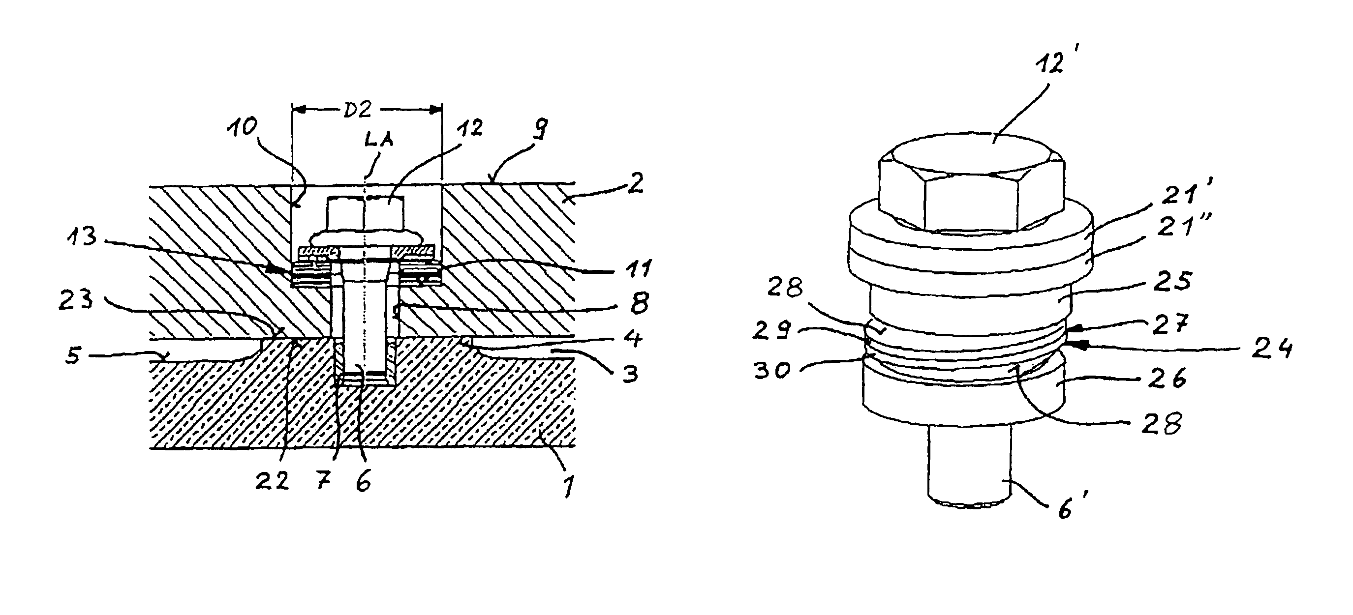
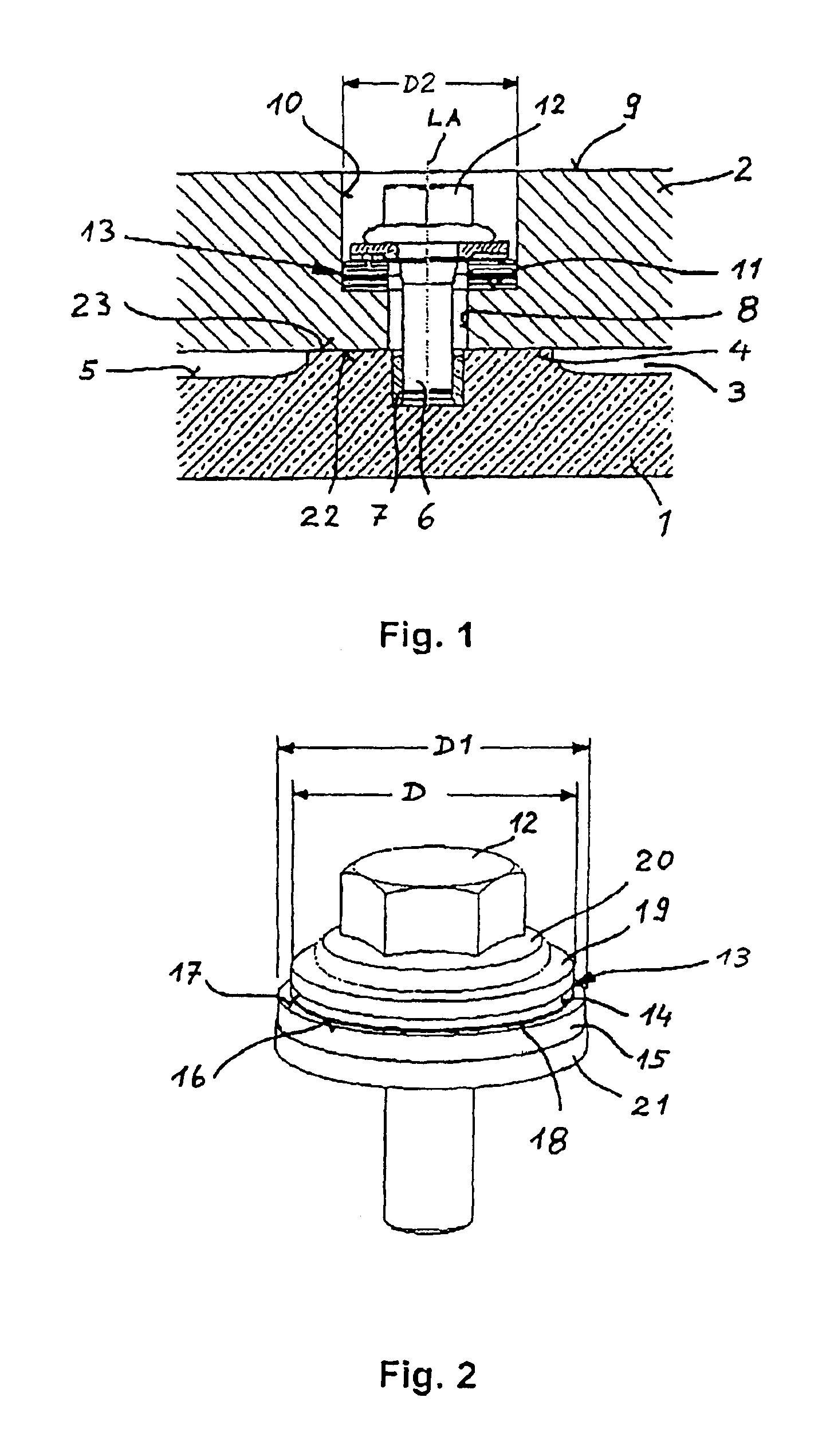
FIG. 1 illustrates in cross section a connection region of a mold plate 1 made of copper or a copper alloy, which on its backside is fastened to a supporting plate 2. Supporting plate 2 may be both an adapter plate as well as a component of a cooling-water tank that is not shown in greater detail.

In this exemplary embodiment, a cooling gap 3 is formed between mold plate 1 and supporting plate 2, which has a cooling arrangement flowing through it. This cooling gap extends between plateau pedestals 4, positioned at a distance from one another, which rise in insular form from cooling arrangement side 5 of mold plate 1. In the plateau pedestal 4 illustrated, a bolt 6 is centrically screwed in. Bolt 6 seats in a screw thread insert 7 in pedestal 4. Bolt 6 penetrates with play a through-hole 8 in supporting plate 2. In the direction towards backside 9 of supporting plate 2, through-hole 8 is widened in diameter to a cylindrical countersink 10. At bore bottom 11 of countersink 10, extendin...


PUM

PropertyMeasurementUnit
diameteraaaaaaaaaa
diameteraaaaaaaaaa
diameteraaaaaaaaaa

Abstract

A liquid-cooled mold for the continuous casting of metals, including mold plates made of copper or a copper alloy, which are supported at their rear on supporting plates by the use of a plurality of bolts. The bolts have bolt heads in the region of the backsides of the supporting plates facing away from the mold plates. Between the bolt heads and the supporting plate an articulation system making possible relative motion between the mold plate and the supporting plates is incorporated, having two articulation members, between which a sliding element is undetachably embedded.

Description

FIELD OF THE INVENTIONThe present invention relates to a liquid-cooled mold for the continuous casting of metals.BACKGROUND INFORMATIONA continuous casting mold for metals is described in German Published Patent No. 195 81 604 T1, in which a uniformly thick mold plate made of copper or a copper material is connected to a support plate made of steel via a plurality of bolts. As a result of the thermally caused expansion of the mold plates in the casting operation, there comes about, particularly in the case of short bolts, a non-negligible bending stress and tensile stress in the bolts. Depending on the fastening of the bolts to the mold plate, in the case of welded-on bolts, failure of the welding connection may occur, or, in the case of screwed-in bolts, overstressing of the thread may occur. In the extreme case, cracks in the mold plate may even occur. In order to avoid this, it is provided in German Published Patent No. 195 81 604 T1 that one may bolt together the mold plate and ...

Claims


Application Information

Patent Timeline
Patent Type & Authority Patents(United States)
IPC IPC(8): B22D11/055B22D11/059B22D11/04B22D11/22
CPCB22D11/059B22D11/055B22D11/22
Inventor HUGENSCHUTT, GERHARDROLF, THOMASKOLBECK, DIETMARWOBKER, HANS-GUNTER
Owner KME GERMANY GMBH & CO KG
Learn More