Sacrificial stinger impact absorber

Active Publication Date: 2011-11-08
ITREC BV
View PDF7 Cites 4 Cited by
  • Summary
  • Abstract
  • Description
  • Claims
  • Application Information

AI Technical Summary

Benefits of technology

[0013]It is known that a freak wave can occur even under relatively calm conditions, so that no precautions can be taken (e.g. changing heading of the vessel, suspending) to counter the effect of the freak wave. A freak wave can e.g. have a wave height of about 10 meters, with the effect that the passage of the wave will throw the stinger up and down violently. Without sacrificial absorber extensive damage must be feared which reduces the operational efficiency of the vessel. The use of a sacrificial absorber compared to e.g. a fluidic shock absorber based on fluid pressure or fluid flow (restriction) is advantageous in view of the costs for an absorber which has to absorb the enormous impact caused by a violent motion of a stinger.

Problems solved by technology

Without sacrificial absorber extensive damage must be feared which reduces the operational efficiency of the vessel.

Method used


Image

  • Sacrificial stinger impact absorber
  • Sacrificial stinger impact absorber
  • Sacrificial stinger impact absorber

Examples


Embodiment Construction

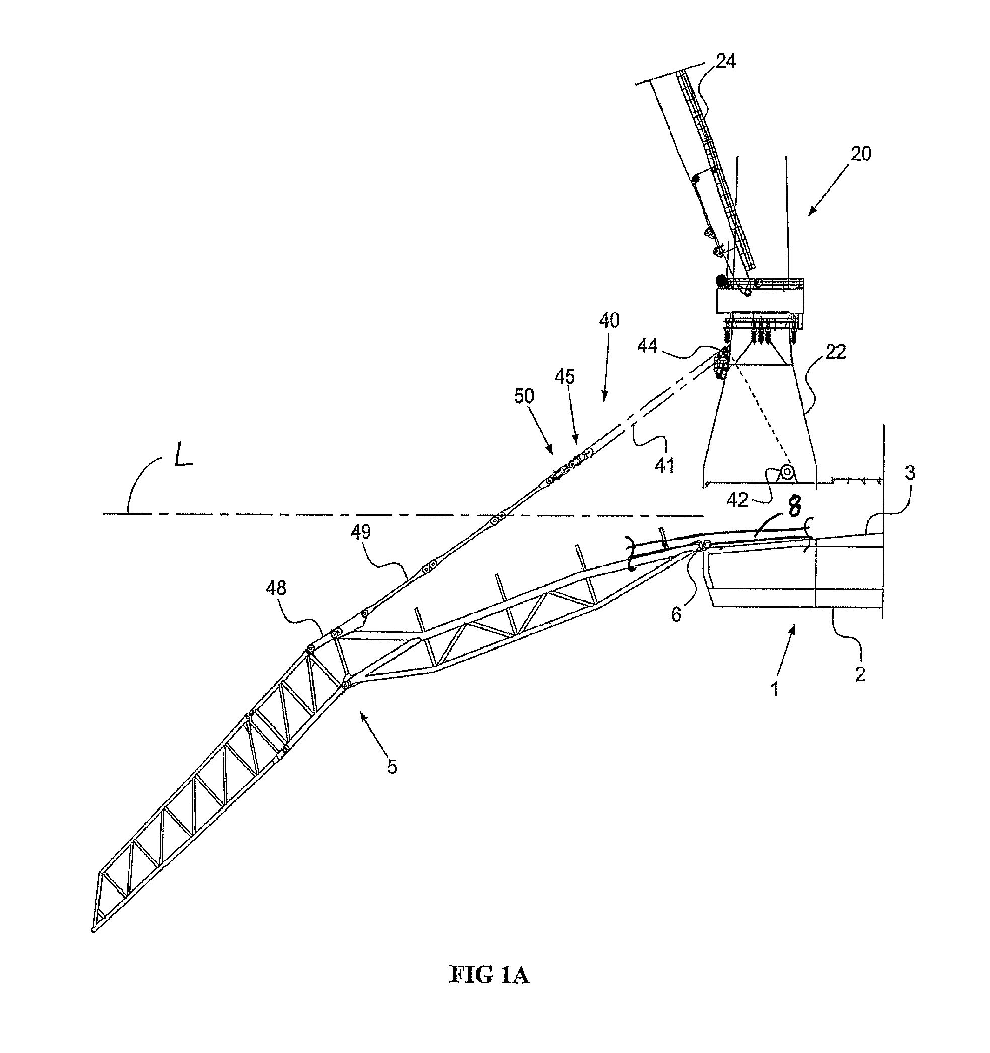
[0024]FIG. 1A shows a stern part of an offshore vessel 1 which is suitable, inter alia, for laying a pipeline on the seabed. The vessel 1 has a hull 2 with a working deck 3. The vessel 1 here is provided with a pipeline-laying installation of the S-lay type, with one or more welding stations (not shown) on the working deck 3, for coupling pipeline sections in a substantially horizontal orientation. On the working deck 3 there are also what are known as tensioners (not shown) for carrying the weight of the pipeline which is hanging downwards from the vessel to the seabed.

[0025]Furthermore, the vessel 1 has a stinger 5 which projects outside the hull 2 of the vessel 1 at the rear side of the vessel 1, engages on the hull 2 at an engagement point such that it can pivot about a substantially horizontal pivot structure 6 and forms a downwardly curved support for pipeline 8 (a part is depicted only) moving towards the seabed. Furthermore, the vessel 1 has a hoisting crane 20, disposed in ...


PUM


Abstract

A marine pipelaying vessel with a pipeline stinger connected to said vessel, preferably pivotable, and forming a downwardly directed support for pipeline to be laid. The vessel further includes a stinger suspension assembly between the stinger and the vessel from which the stinger is suspended at least during operation, preferably the stinger suspension assembly allowing to lower and raise said stinger. The stinger suspension assembly includes a sacrificial stinger impact absorber which is adapted to absorb impact energy resulting from a violent stinger motion, e.g. induced by a freak wave. Preferably, the impact absorber forms an elongatable structure, e.g. a telescopic structure, which is elongated under impact energy absorption.

Description

BACKGROUND OF THE INVENTION[0001]1. Field of the Invention[0002]The present invention relates to the field of marine pipelaying, wherein a pipeline is laid from an offshore vessel onto the seabed.[0003]2. Description of Background Art[0004]In this field is it known to use a pipeline supporting stinger to support the pipeline from the vessel into the water. The vessel can be of any suitable design, including a monohull vessel, a semi-submersible, a barge, etc. Often said stinger provides a curved or semi-curved path for the pipeline, e.g. when the pipeline is assembled or paid out in a generally horizontal direction from the vessel. The design of the stinger commonly depends on factors like the envisaged water depth, pipeline size and weight, pipeline properties (stiffness, material(s), possible coating, etc), pipeline tension during laying, etc.[0005]For some years pipelaying has been done or at least proposed for deepwater, which has led to design of very large stingers which allow...

Claims


Application Information

Patent Timeline
IPC IPC(8): F16L1/225
CPCB63B35/03B66C23/52B66C23/82F16L1/225
Inventor ROODENBURG, JOOPROMEIJN, ERIC
Owner ITREC BV
Why Eureka
Try Eureka