Brushless, three phase motor drive

a three-phase, brushless technology, applied in the direction of motor/generator/converter stopper, electronic commutator, dynamo-electric converter control, etc., can solve the problems of reducing efficiency, maintenance issues, and motor friction, so as to increase efficiency, accurately match the required current, and improve the effect of motor performan

Inactive Publication Date: 2011-11-08
MICROCHIP TECH INC
View PDF16 Cites 23 Cited by
  • Summary
  • Abstract
  • Description
  • Claims
  • Application Information

AI Technical Summary

Benefits of technology

[0029]The method then controls operation of the motor based on the one or more time values and the PWM duty cycle. More specifically, the plurality of electromagnets on the stator may be driven by periodic bursts of current whose frequency and power may be specified by the PWM duty cycle in such a way as to drive the rotor at a particular rotational speed, while the one or more time values may determine the commutation timing of the electromagnets on the stator, such that the electromagnetic field of the stator may remain substantially in optimal alignment with the rotor, effecting an efficient transfer of power to the rotor at that particular rotational speed.
[0031]The above method provides significantly greater motor performance, e.g., increased efficiency, as compared to prior art designs. In particular, the above method more accurately matches the required current for a given load to the desired rotational speed by simply responding to the load, effecting more efficient use of energy. In addition, the above method may reduce the frequency with which stall conditions appear, due to the angular velocity truncation step, potentially resulting in smoother performance and additional energy savings. Further, the reduction in complexity of the method over prior art designs allows a more compact and efficient control mechanism design, which further reduces overall power usage.

Problems solved by technology

The use of brushes creates friction in the motor and leads to maintenance issues and reduced efficiency.
The range of complexity in the algorithm varies, with attempts to “soften” the startup current through various techniques, until the BEMF signal can be detected.
These solutions have provided a degree of power savings, but not at the levels anticipated.
Most, if not all of these solutions are designed for a specific motor type, and do not translate well from application to application, or even from manufacturer to manufacturer.
The single largest shortfall of prior art solutions is the lack of power savings realized.
Another source of power inefficiency in some prior art solutions is the lack of “differential commutation”, meaning both the high- and low-side transistors are switched off simultaneously, as a method to control the rotational speed.
Some implementations do not control the frequency or duty cycle of the PWM signals going to the drive transistors, but rather allow the incoming PWM to modulate the signals directly.
The inability to limit either frequency or duty cycle means the motor is not being driven optimally for a given operating point, but is under the control of an external device that may or may not be aware of the motor limitations.
This will cause the motor to use more current than required, producing additional heat that must be removed from the system.
The issue of over-current / lock rotor has also not been properly addressed in some prior art solutions.
In some solutions, there is no provision for this event, and the motor will continue to drive to destruction.
The prior art solutions use a brute-force method to drive the motor coils during start-up, and may last several seconds, drawing several times the normal operating current.
This is one of the drawbacks of the BEMF commutation method.
When cooling any computing platform, power is necessarily consumed to remove heat produced by other components in the system.
As the power consumption of all platforms is reduced, the cooling system consumes power that could either be used to extend battery life in laptops, or to reduce the carbon footprint of server systems.

Method used


Image

  • Brushless, three phase motor drive
  • Brushless, three phase motor drive
  • Brushless, three phase motor drive

Examples


Embodiment Construction

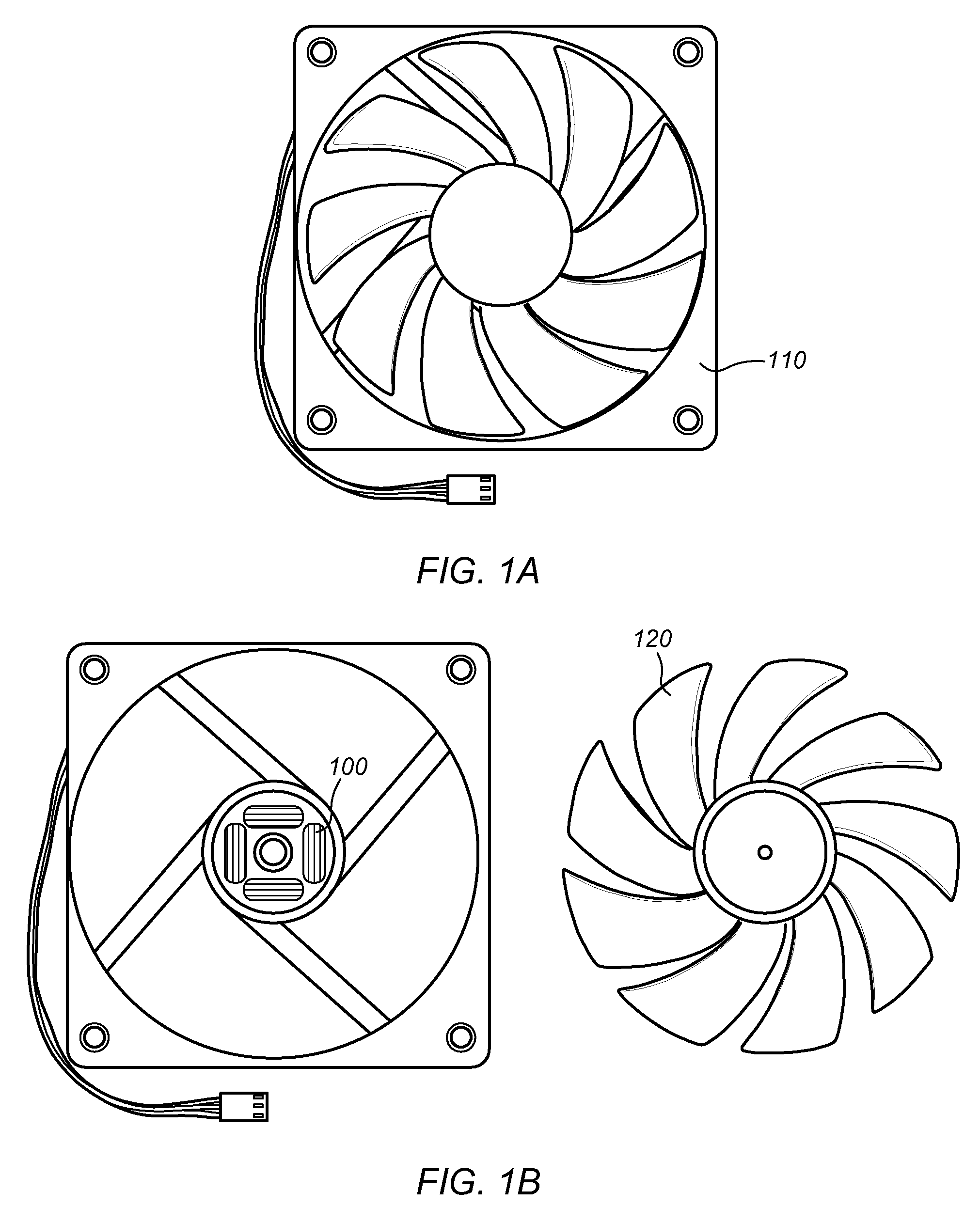
[0042]FIGS. 1A and 1B—Exemplary Fan and Fan Motor

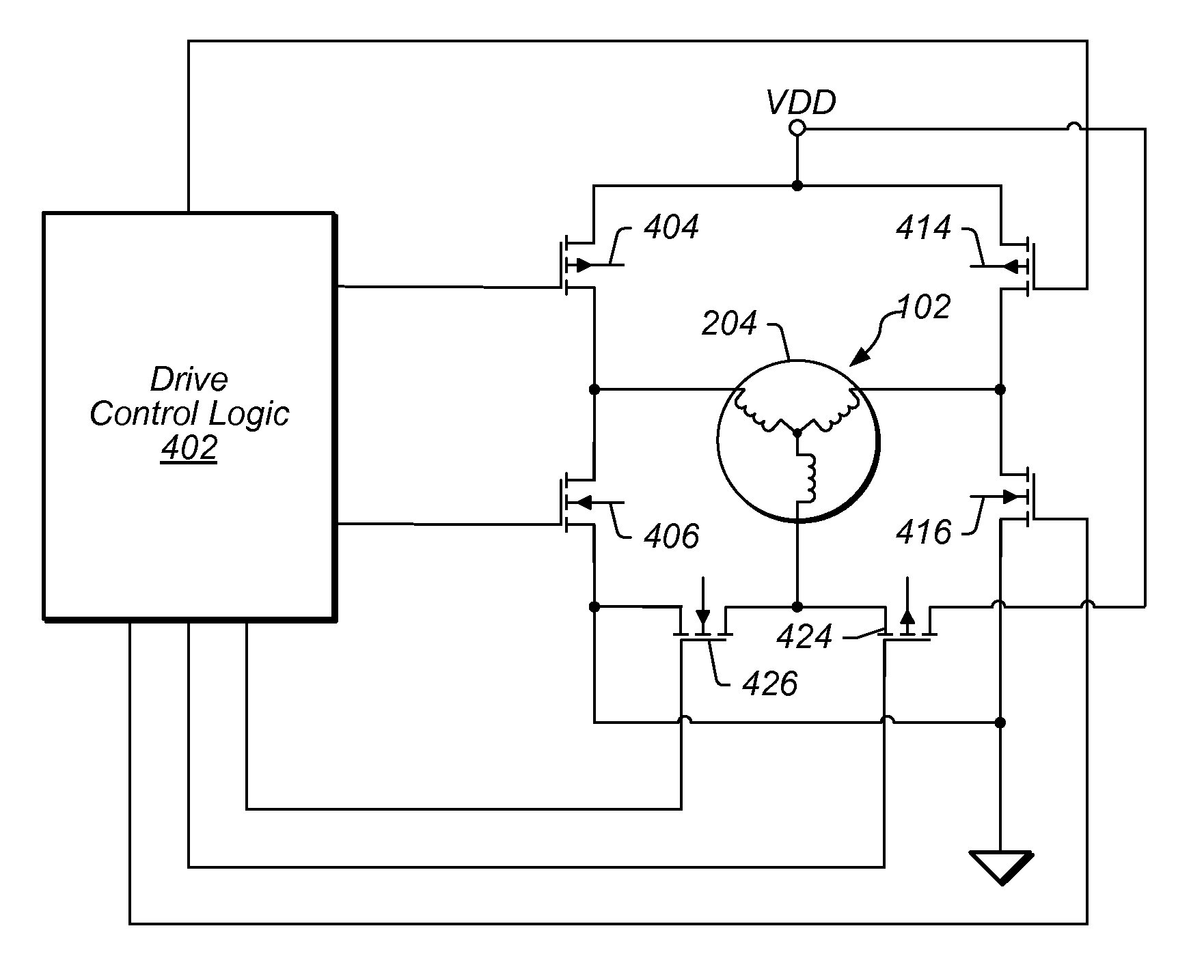
[0043]FIGS. 1A and 1B illustrate an exemplary fan assembly 110 according to one embodiment. The fan 110 may be a cooling fan, for example a fan for use in a laptop or a desktop computer. The fan 110 may alternatively be a commercial or industrial fan, or in general any type of fan driven by a motor. The fan assembly 110 may include a motor assembly 100 as well as fan blades 120. The motor assembly 100 may comprise a motor (102, FIG. 2) as well as drive circuitry (402FIG. 4) for controlling the motor 102.

[0044]Although FIGS. 1A and 1B illustrate a fan as the load being driven by the motor, it should be noted that the system and method for controlling a motor as described herein may be suited for driving any of various types of loads, including without limitation hard disk drives, drive motors for appliances, propellers, wheels, pumps, or other loads.

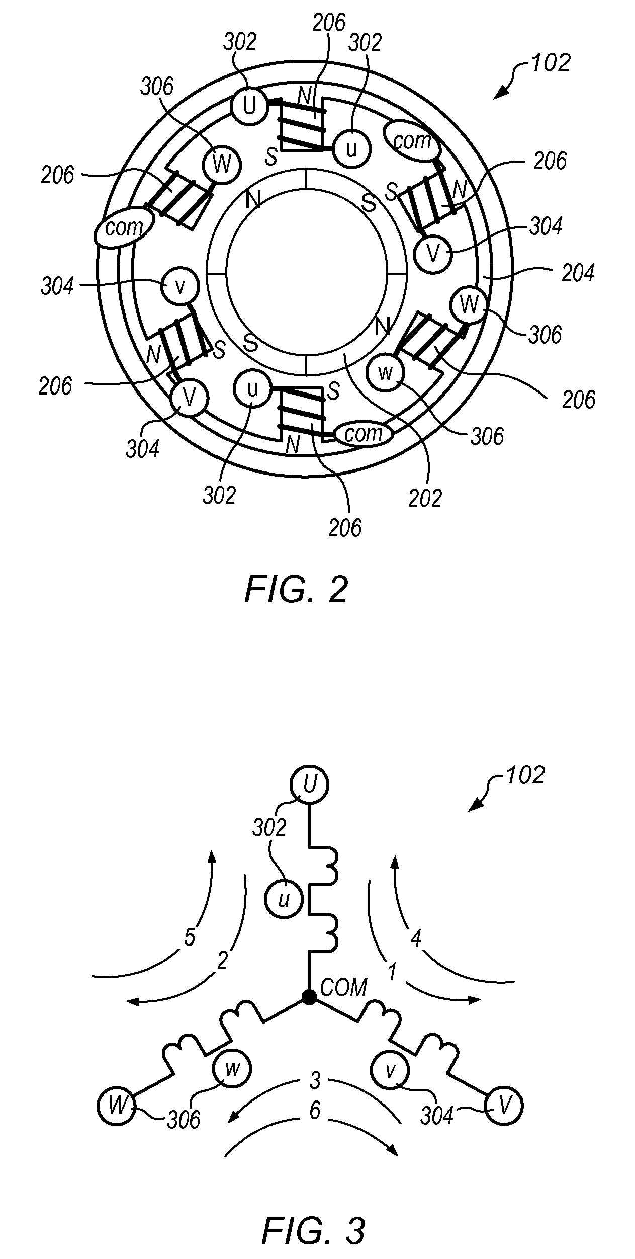
[0045]FIG. 2—Brushless Four-Pole Three-Phase Motor

[0046]FIG. 2 illustrates a simplified...


PUM


Abstract

A control method for a sensor-less, brushless, three-phase DC motor. A pulse-width modulation (PWM) duty cycle may be calculated. A voltage induced by rotation of a rotor may be sampled at a first expected zero crossing value to produce a first sampled voltage value. An average of a plurality of sampled voltage values, including voltage values sampled at a plurality of prior expected zero crossing values and the first sampled voltage value, may be calculated. The first sampled voltage value may be subtracted from the calculated average to produce a delta zero crossing error. The delta zero crossing error may be multiplied by a first constant representing electromechanical properties of the motor to produce a representation of an angular velocity. One or more time values may be generated based on the representation of the angular velocity. Operation of the motor may be controlled based on the one or more time values and the PWM duty cycle.

Description

PRIORITY CLAIM[0001]This application claims benefit of priority of U.S. Provisional Patent Application Ser. No. 61 / 108,320 titled “Sensor-less, Brushless, Three Phase Motor Drive”, filed on Oct. 24, 2008, whose inventor was Lynn R. Kern, and which is hereby incorporated by reference as though fully and completely set forth herein.BACKGROUND OF THE INVENTION[0002]1. Field of the Invention[0003]The invention generally relates to DC (Direct Current) motors used in various applications, such as hard disk drive motors, cooling fans, drive motors for appliances, etc.[0004]2. Description of the Related Art[0005]An electric motor uses electrical energy to produce mechanical energy. Electric motors are used in a large number of applications, including a number of different household appliances, pumps, cooling fans, etc. Motors can generally be classified as either alternating current (AC) motors or direct current (DC) motors.[0006]Motors generally include a rotor, which is the non-stationary...

Claims


Application Information

Patent Timeline
Patent Type & Authority Patents(United States)
IPC IPC(8): H02P23/00
CPCH02P6/182
Inventor KERN, LYNN R.MCFARLAND, JAMES P.
Owner MICROCHIP TECH INC
Why Eureka
Try Eureka