RFID tag power conservation system and method

a power conservation system and tag technology, applied in the field of active bimodal rfid tags, can solve the problems of large and cumbersome passive readers, inability to work, and large power drain of active tags, and achieve the effect of reducing power drain and less power drain

Inactive Publication Date: 2011-11-08
INNOVATION LAW GROUP
View PDF17 Cites 19 Cited by
  • Summary
  • Abstract
  • Description
  • Claims
  • Application Information

AI Technical Summary

Benefits of technology

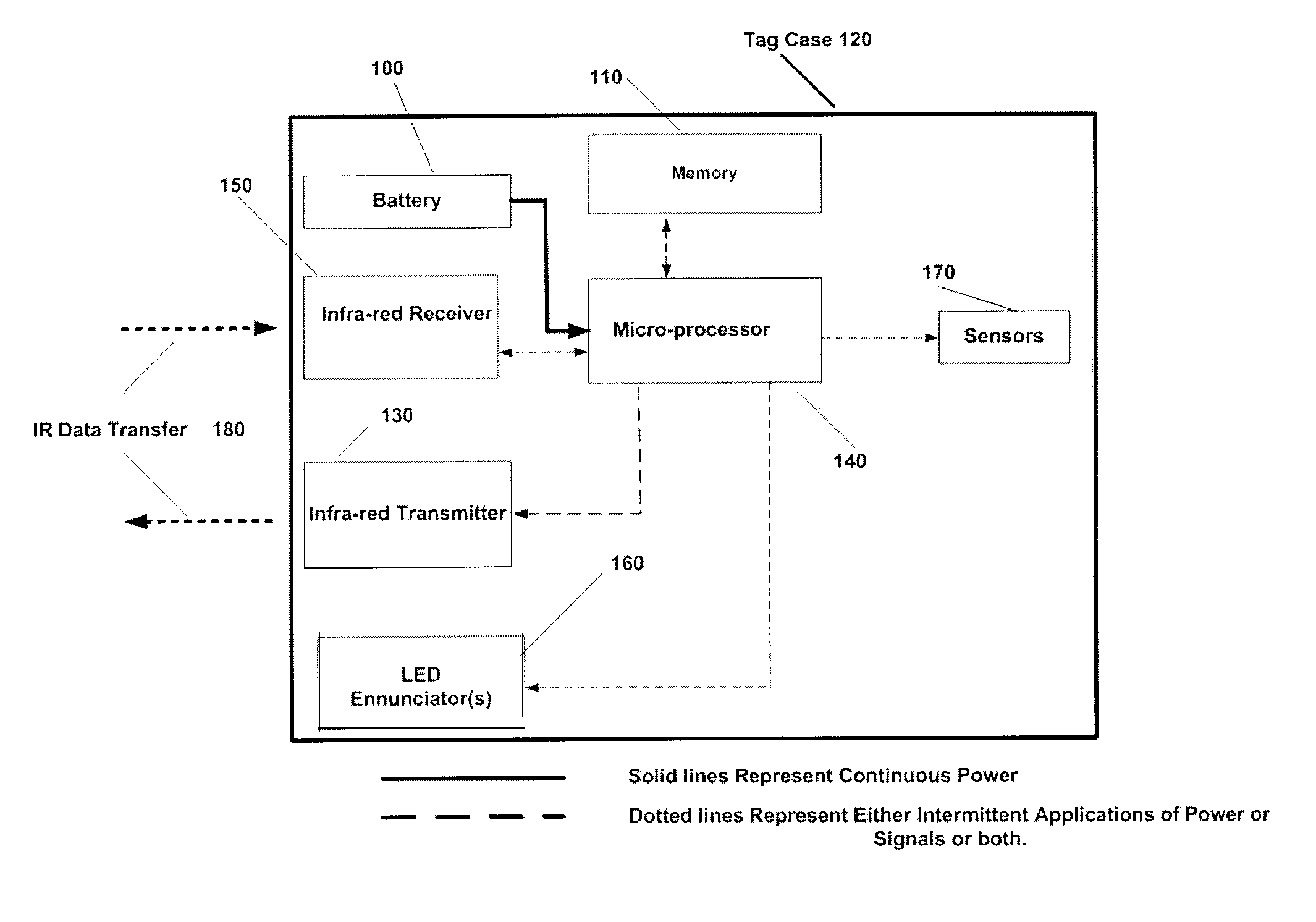
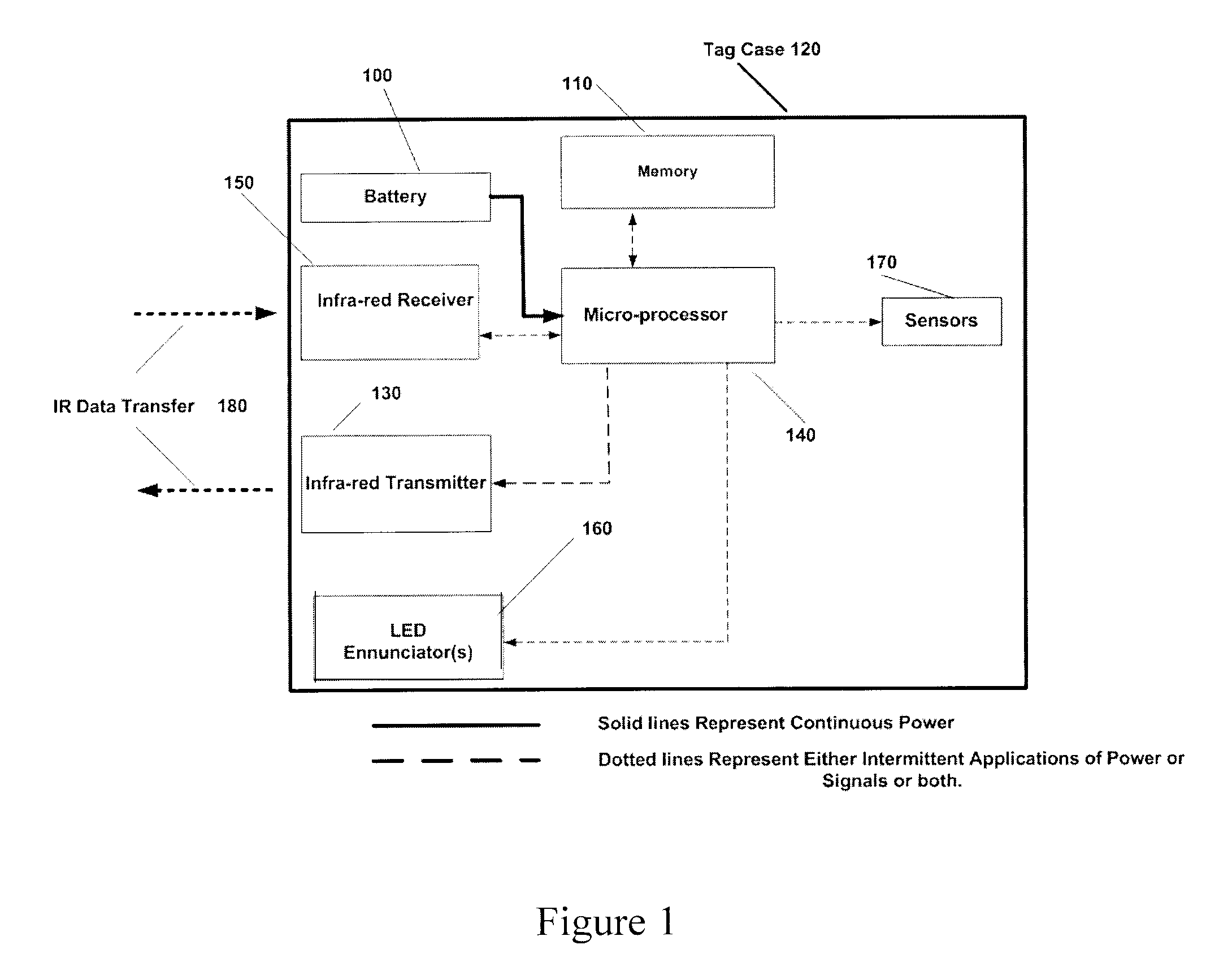
[0012]The invention is directed to active, battery powered, multi-modal RFID tags having RF, IR, US (ultra-sound) and Laser receivers, transmitters or transceivers that are configured primarily for indoor operation, including novel circuit architecture and operational wake-up and scan algorithms for detection of periodic signal beacons from illuminators that result in significant and unexpected improvements in battery life. More particularly, the invention is directed to a paradigm shift in the operational algorithm, enabled in firmware and unique circuitry, that functions to conserve battery power of active, battery powered, bimodal RFID tags so that they have a useful, functional life on the order of 5 to 10 times longer than a tag powered by the same battery but not having the inventive system. The inventive tags are particularly useful when affixed to hard assets or personnel
[0033]In a second embodiment, the tag includes an RC circuit comprising a resistor off the battery to a capacitor. When the capacitor charges, the microprocessor of the inventive bimodal RFID tag wakes up in response to the voltage build up in the capacitor and drains it. The battery then re-charges the capacitor through the resistor. This creates an oscillator circuit that functions as a timer. To reduce power drain the inventive circuit uses a solid state capacitor. This oscillator circuit using the sold state capacitor uses less power drain that the conventional clock circuit used in conventional, prior art, RFID tags. This timer is used to time the interval for the inventive bimodal RFID tag envelope event. The result for this second embodiment is to extend the battery life to 5.4 years, a more than 10-fold improvement over current tags.

Problems solved by technology

If a metallic or water-laden object is in front of the signal, then the tags will be blocked and not work.
Passive readers are large and cumbersome and best suited to fixed installations as field tag read and write capabilities require large readers and direct line of sight.
Active tags perform very well but are higher in cost than passive tags and therefore are restricted to specific applications that can carry a higher unit cost.
However, the cost of replacing drained batteries far exceeds the cost of the product and can be the criteria for selection of one device over another.
However, since they are active tags, they have not had significant impact on the field as they are limited in life by their battery capacity.
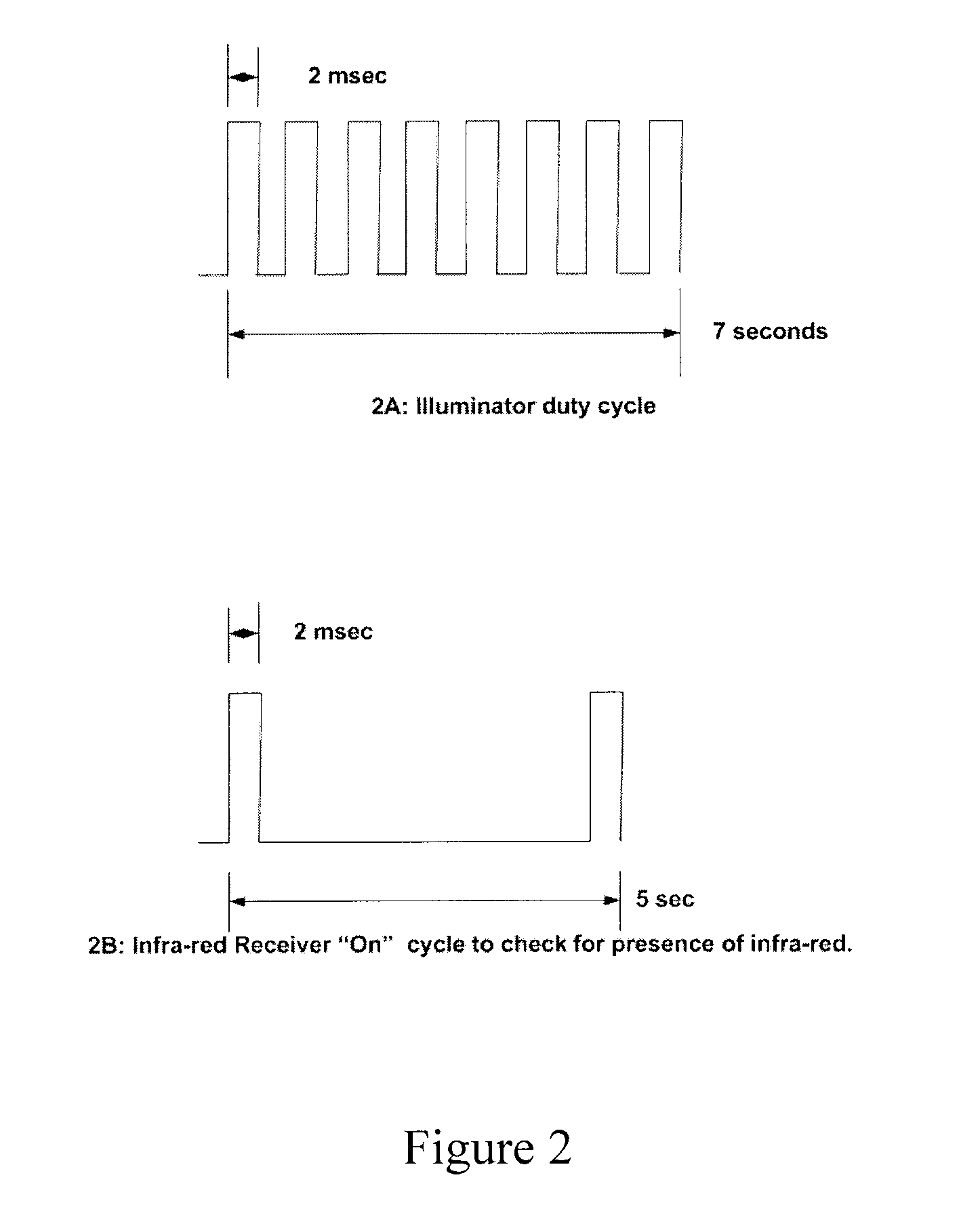
This short battery life is due to the microprocessor instruction set algorithm awakening the tag from a partial power-down state to fully powered every 5 seconds for full processing of any signal detected.
In addition to the cost of replacement batteries, the necessary staff, record keeping and logistic requirements to keep track of battery check and change-out has created a serious financial barrier to the adoption of such tags for such inventory / location systems.
Although there are improvements in battery technology, there is currently nothing on the horizon that promises more than an incremental 10-20% increase in battery life, not enough to change the financial adoption equation for systems employing active bimodal RFID tags.
However, that not only burns out the power supply of the illuminator, but also causes totally unacceptable “black-out” interference with all other equipment that uses IR or RF to communicate, such as televisions, CD players, computer mice and keyboards, radios, networks, and other IR controllers for equipment, including medical and industrial equipment.

Method used


Image

  • RFID tag power conservation system and method
  • RFID tag power conservation system and method
  • RFID tag power conservation system and method

Examples


Embodiment Construction

[0043]The following detailed description illustrates the invention by way of example, not by way of limitation of the scope, equivalents or principles of the invention. This description will clearly enable one skilled in the art to make and use the invention, and describes several embodiments, adaptations, variations, alternatives and uses of the invention, including what is presently believed to be the best modes of carrying out the invention.

[0044]In this regard, the invention is illustrated in the several figures, and is of sufficient complexity that the many parts, interrelationships, and sub-combinations thereof simply cannot be fully illustrated in a single patent-type drawing. For clarity and conciseness, several of the drawings show in schematic, or omit, parts that are not essential in that drawing to a description of a particular feature, aspect or principle of the invention being disclosed. Thus, the best mode embodiment of one feature may be shown in one drawing, and the...


PUM


Abstract

Active multi-modal RFID tags, illuminator / tag / reader systems, circuit architecture and opera-tional algorithms for battery power conservation that extends tag battery life from a typical 6 months to >5 years. The inventive system is particularly useful in asset and person tracking / inventory systems where power conservation is critical. The tag is configured with a micro-processor operational instruction set algorithm, modifiable on the fly via RF or IR, to synchro-nize a periodic tag awaken / sense envelope that overlaps the illuminator trigger pulse cycle and put the tag into deep, power conservation sleep for N periods of illuminator cycles. When the tag sees an illuminator signal with a different ID, or no illuminator signal at all, it transmits that anomaly via RF to a reader. This means the object or person with which the tag is associated has been moved out of the original illuminator field of view, permitting near real time investigation and tracking.

Description

CROSS-REFERENCE TO RELATED APPLICATION[0001]This is the Regular U.S. Application of Provisional Application Ser. No. 60 / 894,152 filed by the same inventors under the same title on Mar. 9, 2007, the priority of which is claimed under 35 US Code Sections 119, 120 ff.FIELD[0002]The invention relates to active bimodal RFID tags, and more particularly to systems, circuit architecture and operational algorithms for conservation of battery power that extends the life of such tags, from a current life of about 6 months, to in excess of 5 years. Such tags are particularly useful in asset tracking and inventory systems in which power conservation is a key commercial criterion.BACKGROUND[0003]Radio Frequency Identification (RFID) applications are proliferating as the economies of automated tracking and identification are being realized by the global community. RFID systems of tags and readers provide the ability to detect, read, and / or write data to tags that are affixed to “things” and / or per...

Claims


Application Information

Patent Timeline
Patent Type & Authority Patents(United States)
IPC IPC(8): H04Q5/22
CPCG06K19/0705G06K19/0723
Inventor CORRADO, ANTHONY P.LOGAN, REX T.
Owner INNOVATION LAW GROUP
Why Eureka
Try Eureka