Mirror effect liquid crystal display device using reflection polarizer

a liquid crystal display and mirror effect technology, applied in non-linear optics, instruments, optics, etc., can solve the problems of display screen not being well visible, lcd device may not give clear pictures at a bright place, and insufficient image brightness of backlight delivered to observers

Active Publication Date: 2011-11-08
LG CHEM LTD
View PDF16 Cites 2 Cited by
  • Summary
  • Abstract
  • Description
  • Claims
  • Application Information

AI Technical Summary

Benefits of technology

The present invention is designed in consideration of the above problems, and therefore it is an object of the invention to provide a LCD device capable of giving a good mirror effect when power is intercepted and also capable of giving a clear display quality using enhanced brightness even at a bright place when power is applied to the device.

Problems solved by technology

As a result, brightness of images delivered to observers from a backlight is not sufficient, so a display screen is not well visible when it is observed at a bright place.
In other words, in case of using a conventional reflector film, the LCD device may give a good mirror effect when power is intercepted, but when power is supplied to the LCD device to display images, the LCD device may not give clear pictures at a bright place due to a reduced contrast caused by inefficient brightness.
Meanwhile, a LCD device has very low luminance efficiency since the light reaching eyes of an observer is not greater than 10% of the light emitted from a light source due to the natures of the device.
However, the DBEF is expensive since anisotropic polymer films and isotropic polymer films are optically laminated alternately.
Also, the DBEF shows deteriorated reflection efficiency since the reflection efficiency is greatly changed depending on a direction of incident light, and a manufacturing process of the DBEF is very complicated.

Method used

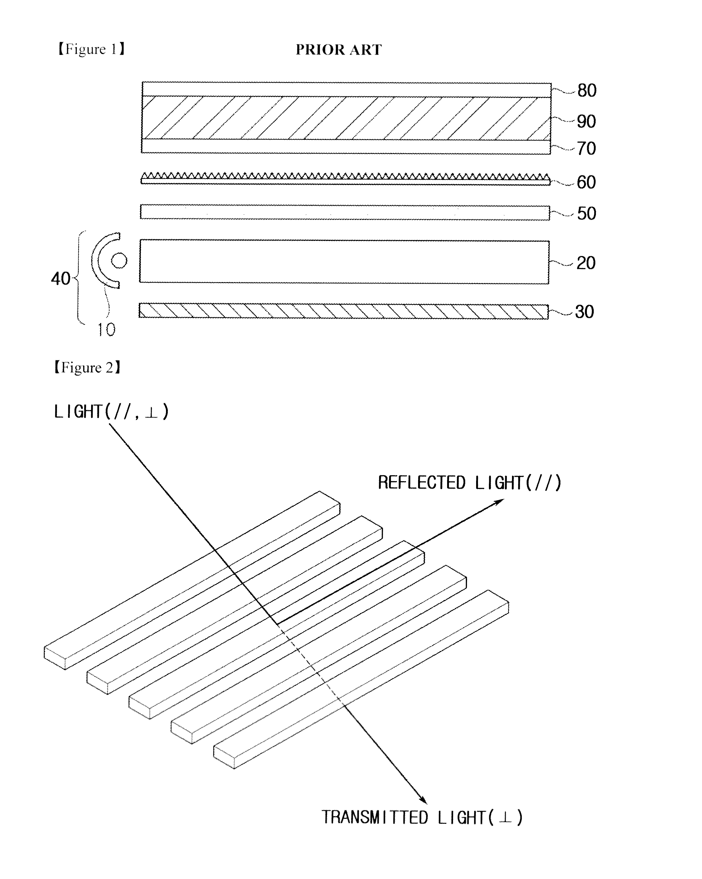
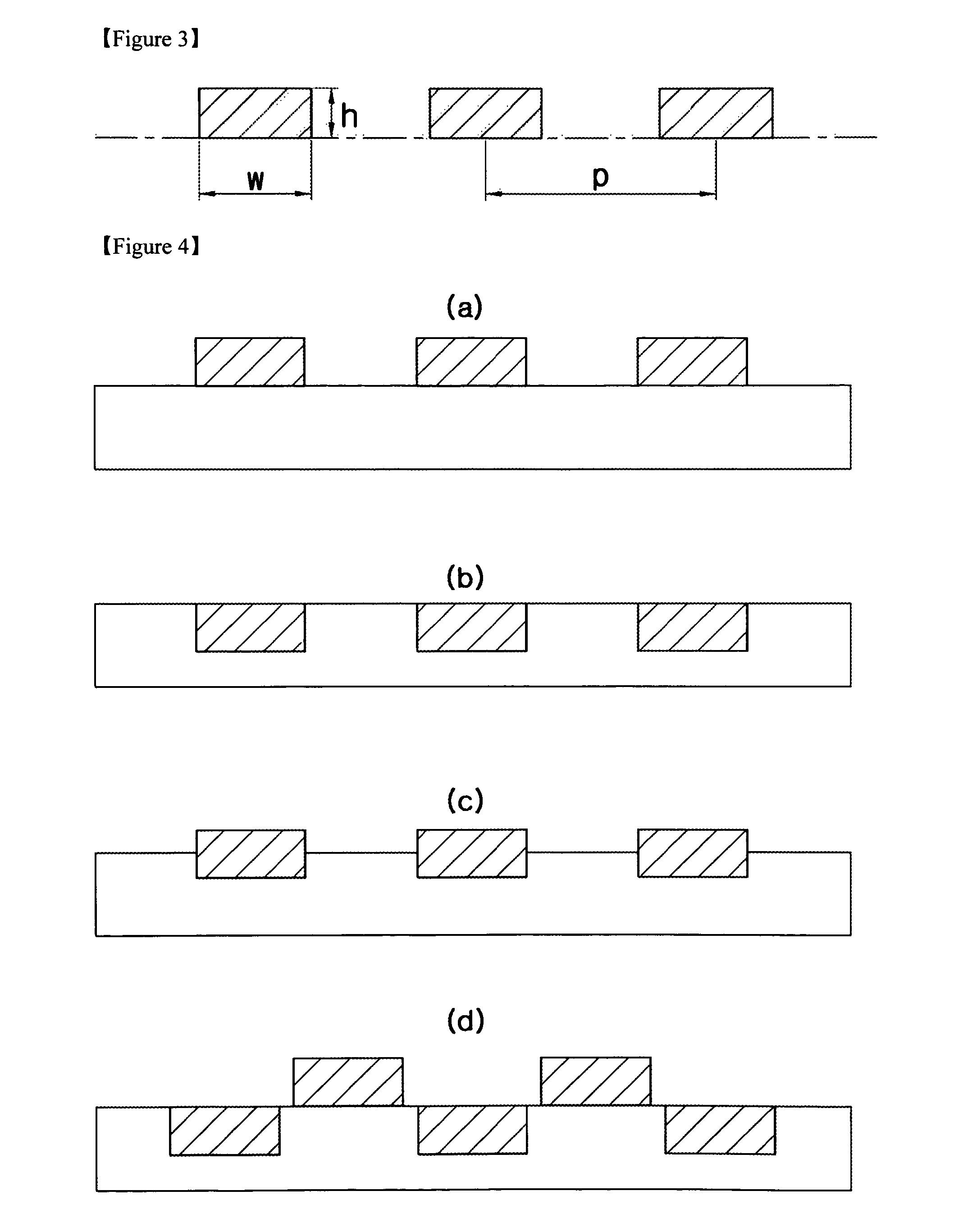

Image

  • Mirror effect liquid crystal display device using reflection polarizer
  • Mirror effect liquid crystal display device using reflection polarizer
  • Mirror effect liquid crystal display device using reflection polarizer

Examples


Embodiment Construction

Hereinafter, preferred embodiments of the present invention will be described in detail with reference to the accompanying drawings. Prior to the description, it should be understood that the terms used in the specification and the appended claims should not be construed as limited to general and dictionary meanings, but interpreted based on the meanings and concepts corresponding to technical aspects of the present invention on the basis of the principle that the inventor is allowed to define terms appropriately for the best explanation. Therefore, the description proposed herein is just a preferable example for the purpose of illustrations only, not intended to limit the scope of the invention, so it should be understood that other equivalents and modifications could be made thereto without departing from the spirit and scope of the invention.

Inventors of the present invention deeply studied to solve the problem of lowered transmittance of a conventional reflector film, and then r...


PUM

PropertyMeasurementUnit
metallicaaaaaaaaaa
transparentaaaaaaaaaa
transmission axisaaaaaaaaaa

Abstract

An LCD (Liquid Crystal Display) device includes a backlight unit, a lower polarizer positioned on the backlight unit, a liquid crystal layer positioned on the lower polarizer, and an upper reflection polarizer positioned on the liquid crystal layer. The upper reflection polarizer is configured such that a regularly arranged metallic line lattice is formed on a support. this LCD device may give a good mirror effect when power is intercepted, and also give a clear display with high brightness even at a bright place when power is supplied to operate the LCD device.

Description

This application claims priority to International Application No. PCT / KR2007 / 004330 filed on Sep. 7, 2007 which claims priority to Korean Patent Application No. 2006-0086571 filed on Sep. 8, 2006, both of which are incorporated by reference, as if fully set forth herein.BACKGROUND ARTAn LCD (Liquid Crystal Display) forms an electric field in a liquid crystal layer to change a pattern of polarized light passing through it such that it may use the phenomenon that light selectively passes through it.At an initial stage, LCD devices are generally applied to a small single-color display of an electronic calculator or a clock. However, along with the progress of LCD techniques, LCD devices are at the present used for large color displays due to the development of AM-TFT technology.In addition, consumers of LCD devices demand not only excellent quality of display that gives clear pictures with a high contrast ratio, high brightness, wide range of view, and prevention of leakage of light, b...

Claims


Application Information

Patent Timeline
Patent Type & Authority Patents(United States)
IPC IPC(8): G02F1/1335
CPCG02F1/133536G02F1/1335
Inventor KIM, TAE-SUSHIN, HYUN-WOOSHIN, BU-GONKIM, JAC-JIN
Owner LG CHEM LTD
Why Eureka
Try Eureka