Method and system for designating a target and generating target-related action

a target and target technology, applied in the field of target designation, can solve the problems of reducing the prospect of duly hitting the target, affecting the calculation of angular error and angular error rate, and low pulse power capacity of the order of 1-4 mjoules per pulse, so as to reduce the prospect of false alarm, increase the prospect of discerning, and low signal/noise ratio

Active Publication Date: 2011-11-08
ISRAEL AEROSPACE IND
View PDF9 Cites 12 Cited by
  • Summary
  • Abstract
  • Description
  • Claims
  • Application Information

AI Technical Summary

Benefits of technology

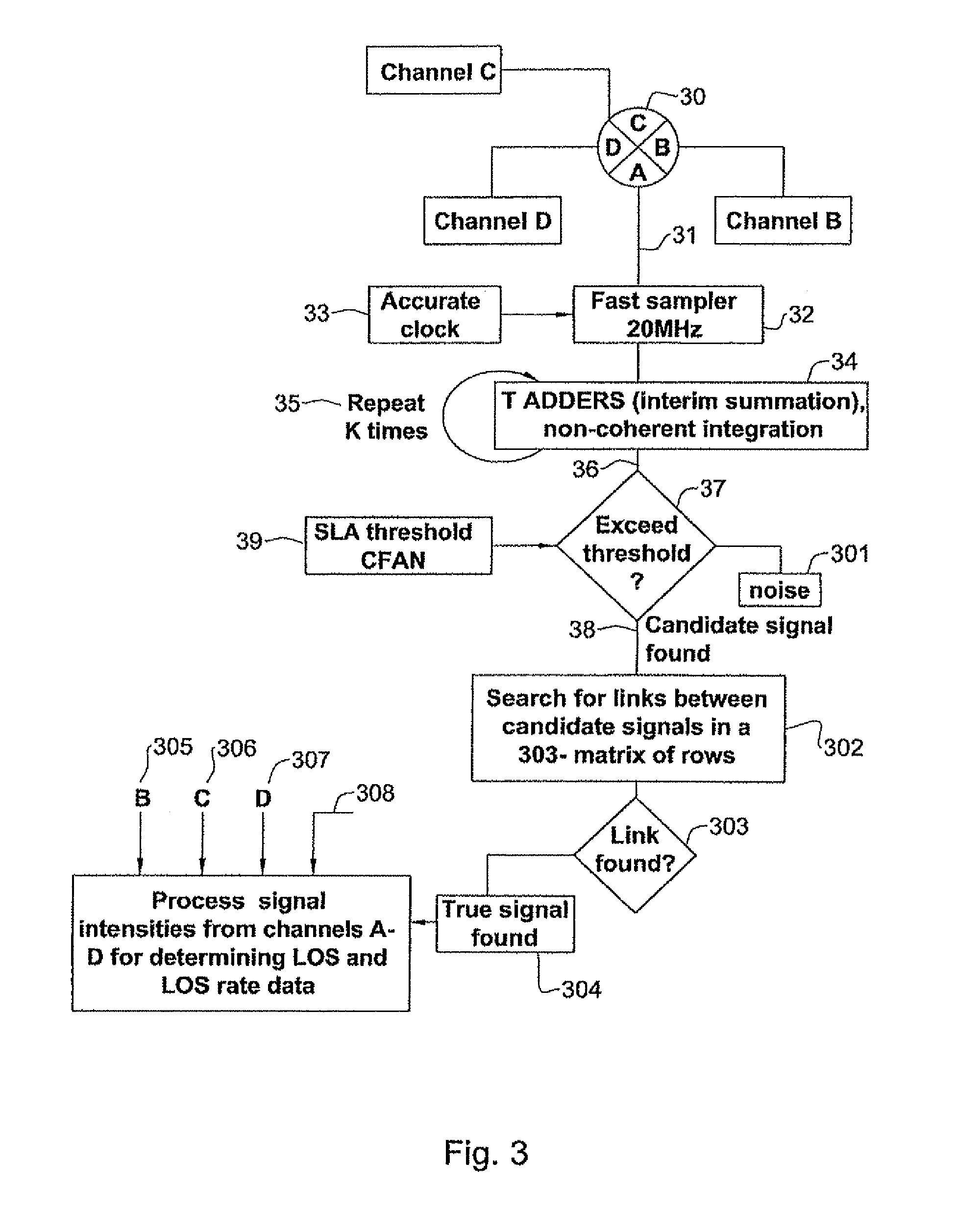
[0026]As readily arises, in accordance with certain embodiments, the invention provides a technique for increasing the prospects of discerning between signal and noise for obtaining at least one true reflected signal notwithstanding an inherent low Signal / Noise ratio of the received signal, or decreasing the prospects of false alarm, namely detecting what appears to be a true signal, but in fact is not.

Problems solved by technology

In case the energy received at the sensor is too low, this will hinder properly. discerning between the signal and noise, thereby adversely affecting the calculation of the angular error and angular error rate, and thereby degrading the prospects of duly hitting the target.
The hitherto known techniques suffer from one or more of the following limitations, including:The relatively high price tag of the laser designator (which illuminates the target) that meets the specified operational specification,The relatively large physical dimensions of the laser designator as well as the relatively high weight which hinders the possibility to carry portable laser designators by a person such as an infantry individual, or fitting them in, a vehicle, such as small flying platforms (for instance UAV) which can fly under the clouds.
Such lasers are in many cases considerably lighter and cheaper than the specified laser designators, but they have low pulse power capacity of the order of 1-4 mjoules per pulse.

Method used


Image

  • Method and system for designating a target and generating target-related action
  • Method and system for designating a target and generating target-related action
  • Method and system for designating a target and generating target-related action

Examples


Embodiment Construction

[0035]The invention is described, for convenience only with reference to intercepting targets. The invention is not bound to this particular application. Other non-limiting target related actions may be applicable, such as displaying target data, measuring distance to target and / or relative velocity and / or others.

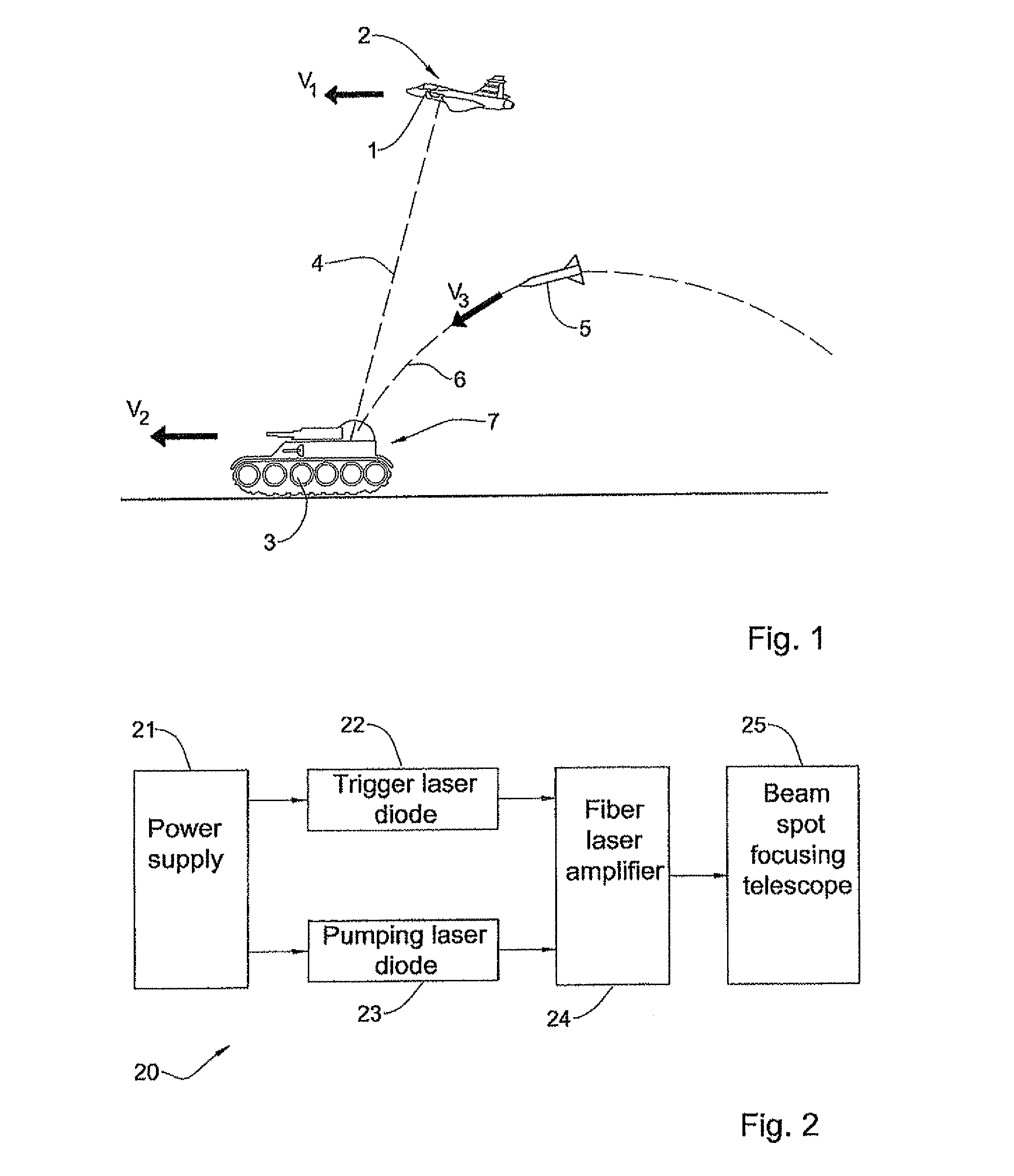
[0036]Note that the specific system specifications provided above (e.g. with reference to FIGS. 1 and 2) and below, are for illustrative purposes only and are by no means binding. Thus, for example, the invention is not bound by the use of fiber optics lasers, and a fortiori not by the specific system architecture of FIG. 2. Typical, yet not exclusive, examples of fiber optics lasers are 10-20 W pulsed fiber lasers, commercially available from SPI lasers company, or YLP high energy pulsed ytterbium Fiber Lasers, commercially available from IPG Photonics Lasers company.

[0037]The invention is described with reference to lasers generating pulses at high frequency (say, at leas...


PUM


Abstract

A system that includes a laser designator configured to continuously designate a target with a pulsed laser spot. The system includes a sensor and associated processing system configured to receive a reflection of the laser spot, convert the received energy to plurality of signals, processing the signals for detecting true reflected signals and process the true reflected signals for generating target related action. The sensor and associated processor are configured to detect the true signals notwithstanding an inherent low Signal / Noise ratio of below 4 of the received signals from due to low pulse power of the laser designator and distance to target.

Description

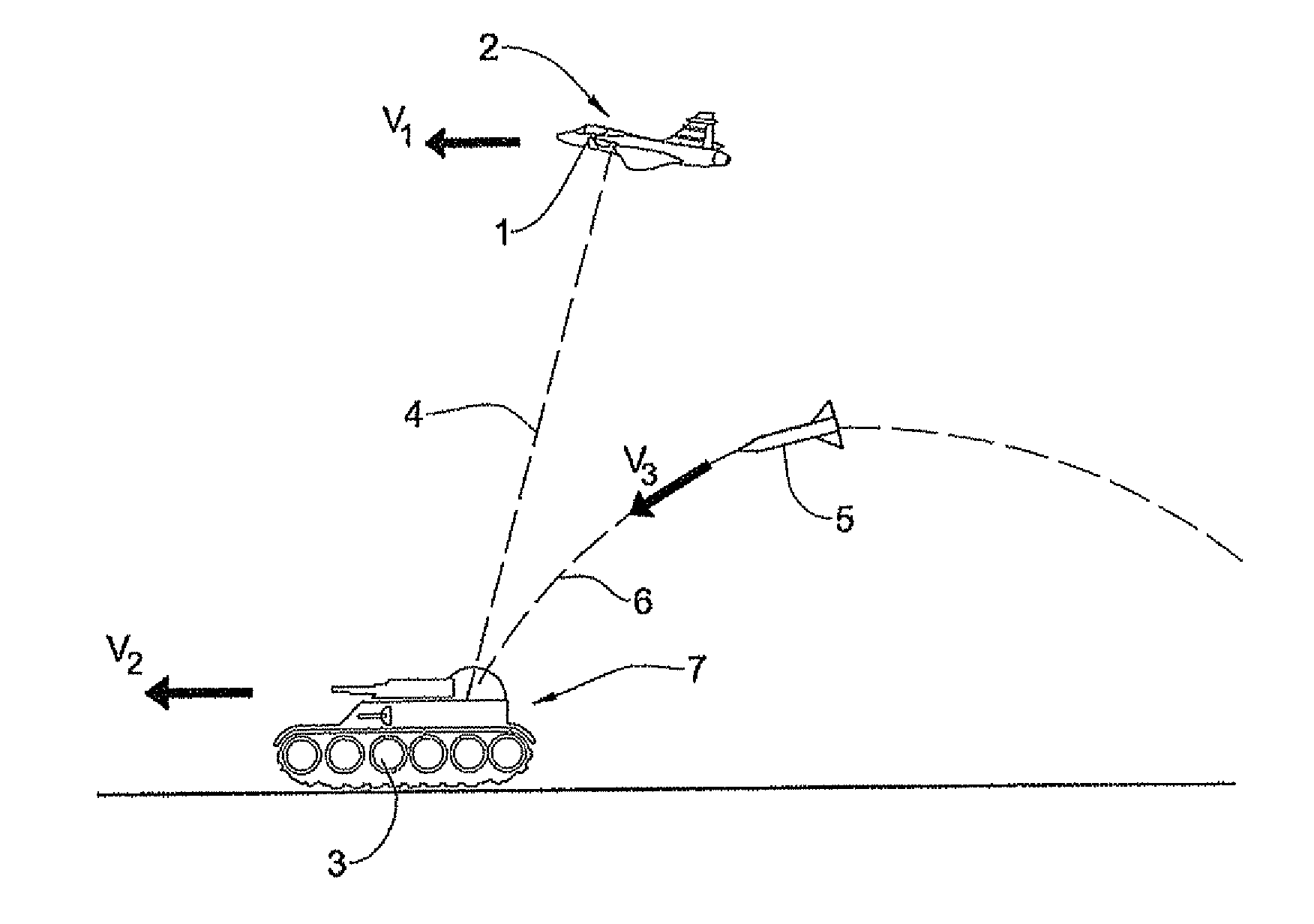
FIELD OF THE INVENTION[0001]This invention relates to designating targets using laser e.g. for homing intercepting objects onto the target.BACKGROUND OF THE INVENTION[0002]Designating targets using laser spots is a widely known technique due to the high precision of the pointing laser device and the relatively low cost of the homing head that utilizes a sensor which receives the energy reflected from the illuminated target, and then processing it for generating steering commands for homing the intercepting platform (such as an intercepting missile) towards the target (such as a moving vehicle).[0003]In accordance with known laser spot guiding techniques (as illustrated schematically in FIG. 1), a laser designator 1 fitted on a given platform 2 constantly tracks the target 3 and illuminates it in a laser beam 4 pulsed spot. Also shown is an intercepting missile 5 employing a sensitive sensor. The sensor's surface is usually divided into four equal sectors (not shown in FIG. 1) and as...

Claims


Application Information

Patent Timeline
Patent Type & Authority Patents(United States)
IPC IPC(8): G01C3/08
CPCF41G3/145F41G7/226G01S7/4873G01S17/66F41G7/2293
Inventor KARAZI, URILEVY, BENJAMINLEVY, RAPHAEL E.HEYMANN, VALERY
Owner ISRAEL AEROSPACE IND
Why Eureka
Try Eureka