Method for inspecting a foreign matter on mirror-finished substrate
a technology of mirror-finished substrate and foreign matter, applied in the direction of image enhancement, instruments, image data processing, etc., can solve the problems of a large amount of time and effort required in writing signals over a multiplicity of tracks, a large amount of cost, and the need for many servo writers and maintenance/managing
- Summary
- Abstract
- Description
- Claims
- Application Information
AI Technical Summary
Benefits of technology
Problems solved by technology
Method used
Image
Examples
embodiment 1
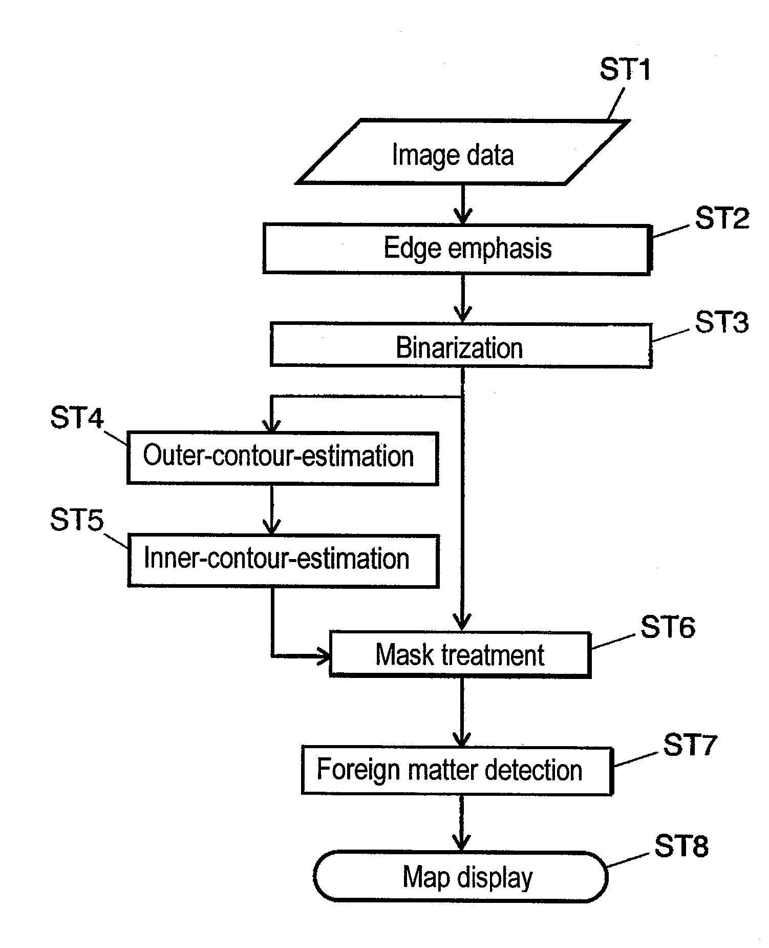
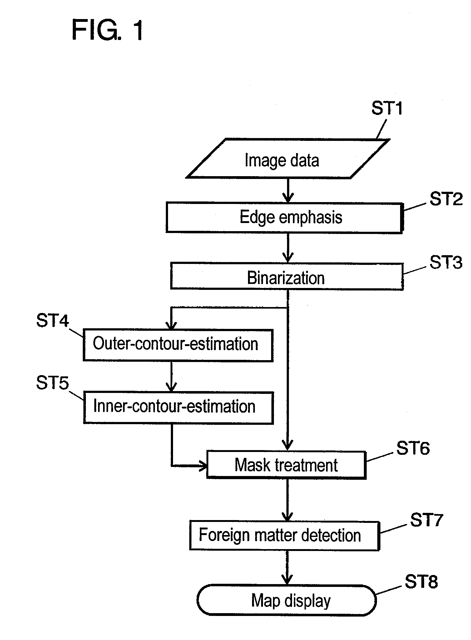
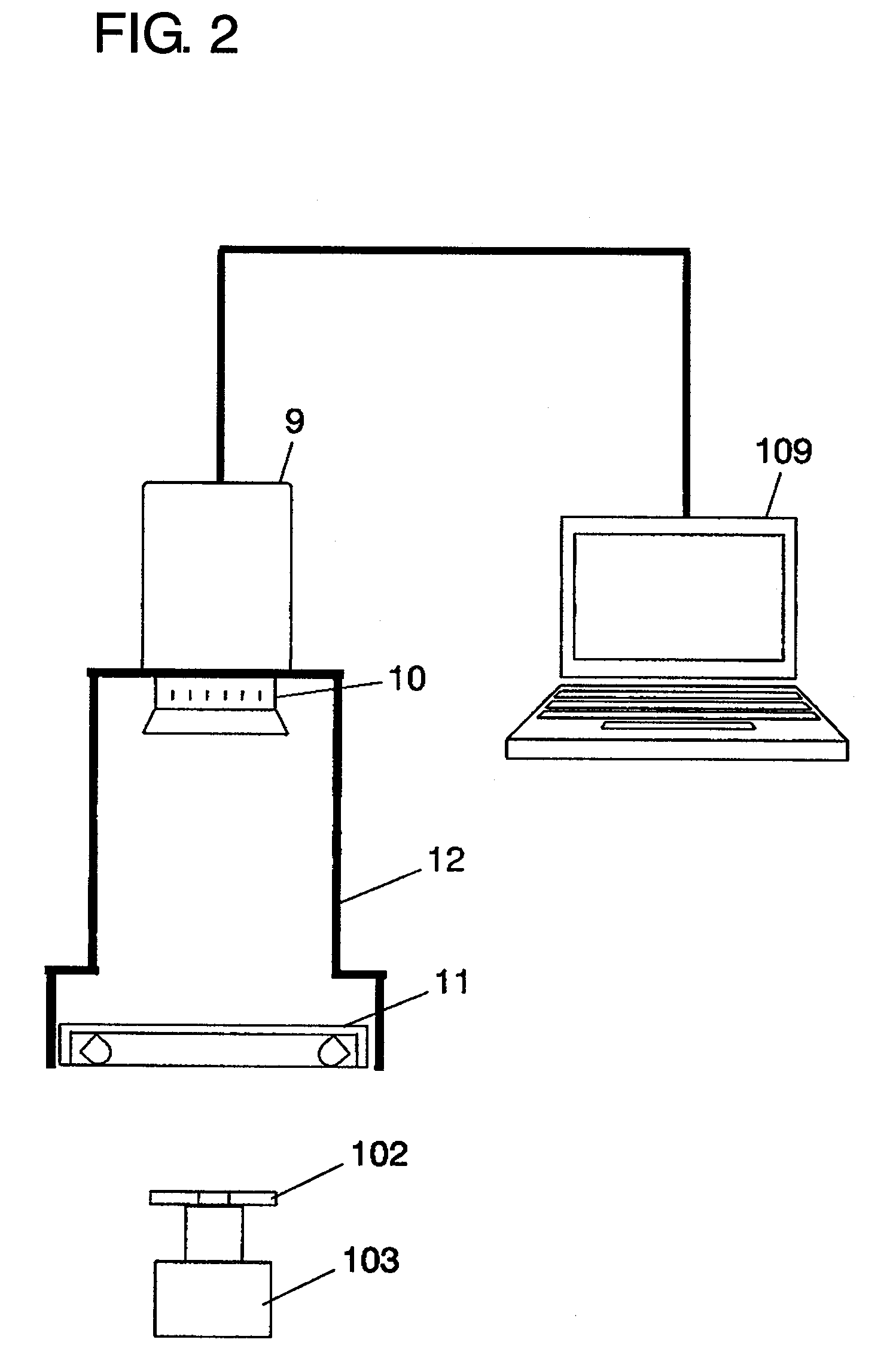
[0076]FIGS. 1 to 11 are figures explaining a foreign matter inspection method on mirror-finished substrate according to embodiment 1 of the present invention. FIG. 1 is a flowchart of the foreign matter inspection method on mirror-finished substrate according to embodiment 1 of the present invention. FIG. 2 is a schematic diagram of an inspection apparatus to be used in step ST1. FIG. 3 is a broken-away perspective view of a magnetic disk, for showing a relationship between illumination light and reflection light. FIG. 4 is a figure showing image data. FIG. 5 is a figure showing the image data emphasized at edges. FIG. 6 is a figure showing the image data processed with binarization. FIG. 7 is a plan view showing how to detect a sampling point at outer periphery. FIG. 8 is a plan view showing how to detect a sampling point at inner periphery. FIG. 9 is a figure showing mask image data. FIG. 10 is a figure showing the mask-treated image data. FIG. 11 is a map figure showing the coord...
embodiment 2
[0121]FIG. 12 is a schematic diagram of an inspection apparatus for explaining a foreign matter inspection method on mirror-finished substrate according to embodiment 2 of the present invention. FIG. 13 is a figure showing the image data obtained by the relevant inspection apparatus.
[0122]In FIG. 12, irregular reflection plate 16 is to irregularly reflect the illumination light of from LED illuminator 11. The inspection apparatus of embodiment 2 differs from embodiment 1 in that magnetic disk 102 is rested on irregular reflection plate 16. The others are identical to the inspection apparatus of embodiment 1, and hence omitted to explain.
[0123]FIG. 13 is a figure showing the image data acquired by the inspection apparatus shown in FIG. 12. Irregular-reflection-plate images Z6, Z7 are captured by introducing the reflection light upon irregular reflection plate 16 to imager device 9. By thus providing irregular reflection plate 16, contours of mirror-finished surface 13 of magnetic dis...
PUM
 Abstract
Description
Claims
Application Information
 - R&D
- Intellectual Property
- Life Sciences
- Materials
- Tech Scout
- Unparalleled Data Quality
- Higher Quality Content
- 60% Fewer Hallucinations
Browse by: Latest US Patents, China's latest patents, Technical Efficacy Thesaurus, Application Domain, Technology Topic, Popular Technical Reports.
© 2025 PatSnap. All rights reserved.Legal|Privacy policy|Modern Slavery Act Transparency Statement|Sitemap|About US| Contact US: help@patsnap.com


