System and method for maintaining a distribution of currents in an electrode array using independent voltage sources

a voltage source and current distribution technology, applied in the field of tissue stimulation systems, can solve the problems of reducing the sensitivity of the spatial recruitment of nerve fibers to impedance variations, reducing the therapeutic efficacy and/or patient comfort, and regulated output pulses

Active Publication Date: 2011-11-08
BOSTON SCI NEUROMODULATION CORP
View PDF124 Cites 88 Cited by
  • Summary
  • Abstract
  • Description
  • Claims
  • Application Information

AI Technical Summary

Problems solved by technology

However, the number of electrodes available, combined with the ability to generate a variety of complex stimulation pulses, presents a huge selection of stimulation parameter sets to the clinician or patient.
Thus, correct lead placement can mean the difference between effective and ineffective pain therapy.
Thus, because current, as opposed to voltage, is most directly related to stimulation strength, the use of current regulated output pulses reduces the sensitivity of the spatial recruitment of nerve fibers to impedance variations.
This is not the case, however, when output pulses are voltage regulated, since the current on each active electrode will vary with the change in impedance.
Even a small change in the current distribution on the active electrodes can change the spatial recruitment of nerve fibers causing a reduction in therapeutic efficacy and / or patient comfort.
Thus, without some means of adjusting the output voltage distribution on all active electrodes based on impedance variations, the stimulation pattern can change, resulting in reduced therapeutic efficacy.

Method used


Image

  • System and method for maintaining a distribution of currents in an electrode array using independent voltage sources
  • System and method for maintaining a distribution of currents in an electrode array using independent voltage sources
  • System and method for maintaining a distribution of currents in an electrode array using independent voltage sources

Examples


Embodiment Construction

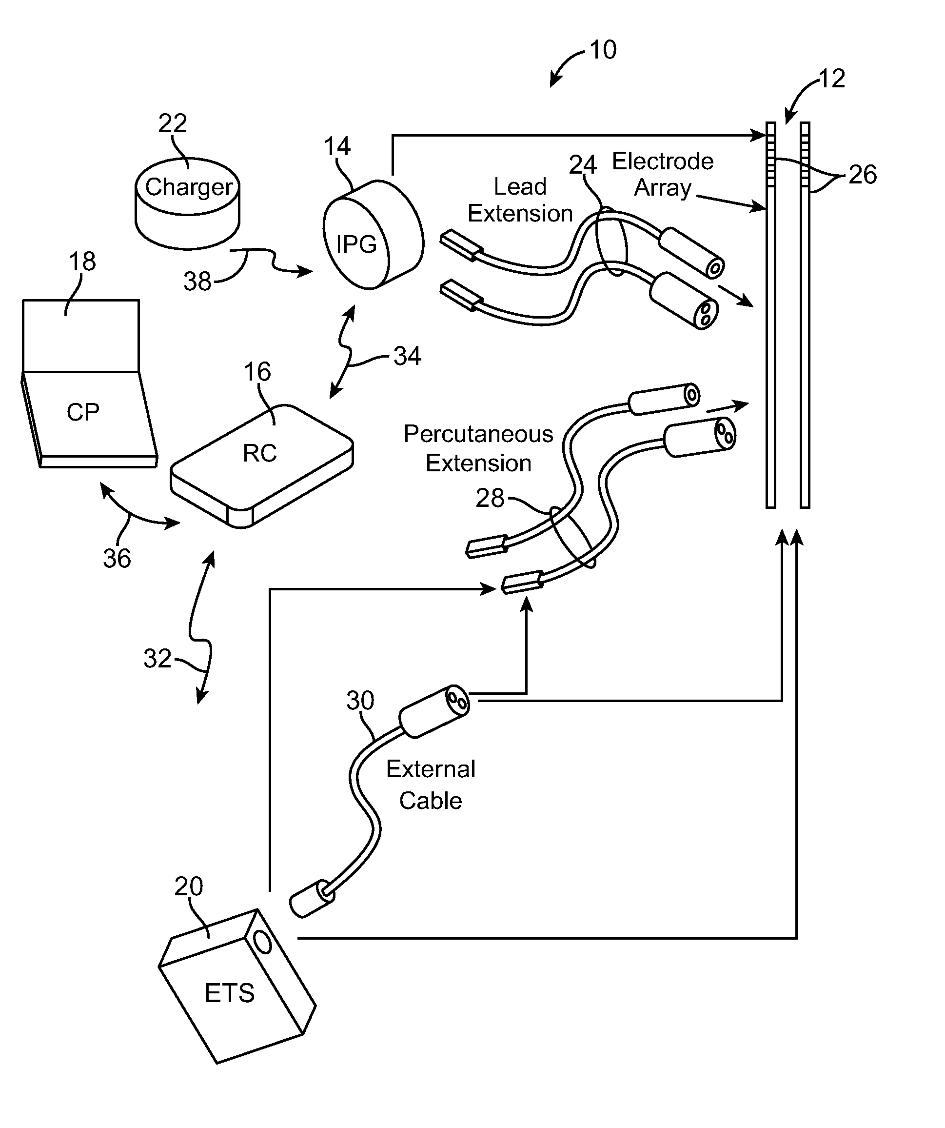
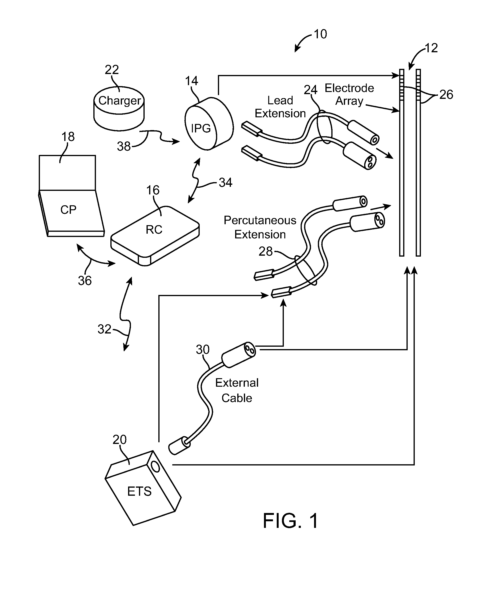
The description that follows relates to a spinal cord stimulation (SCS) system. However, it is to be understood that while the invention lends itself well to applications in SCS, the invention, in its broadest aspects, may not be so limited. Rather, the invention may be used with any type of implantable electrical circuitry used to stimulate tissue. For example, the present invention may be used as part of a pacemaker, a defibrillator, a cochlear stimulator, a retinal stimulator, a stimulator configured to produce coordinated limb movement, a cortical stimulator, a deep brain stimulator, peripheral nerve stimulator, microstimulator, or in any other neural stimulator configured to treat urinary incontinence, sleep apnea, shoulder sublaxation, headache, etc.

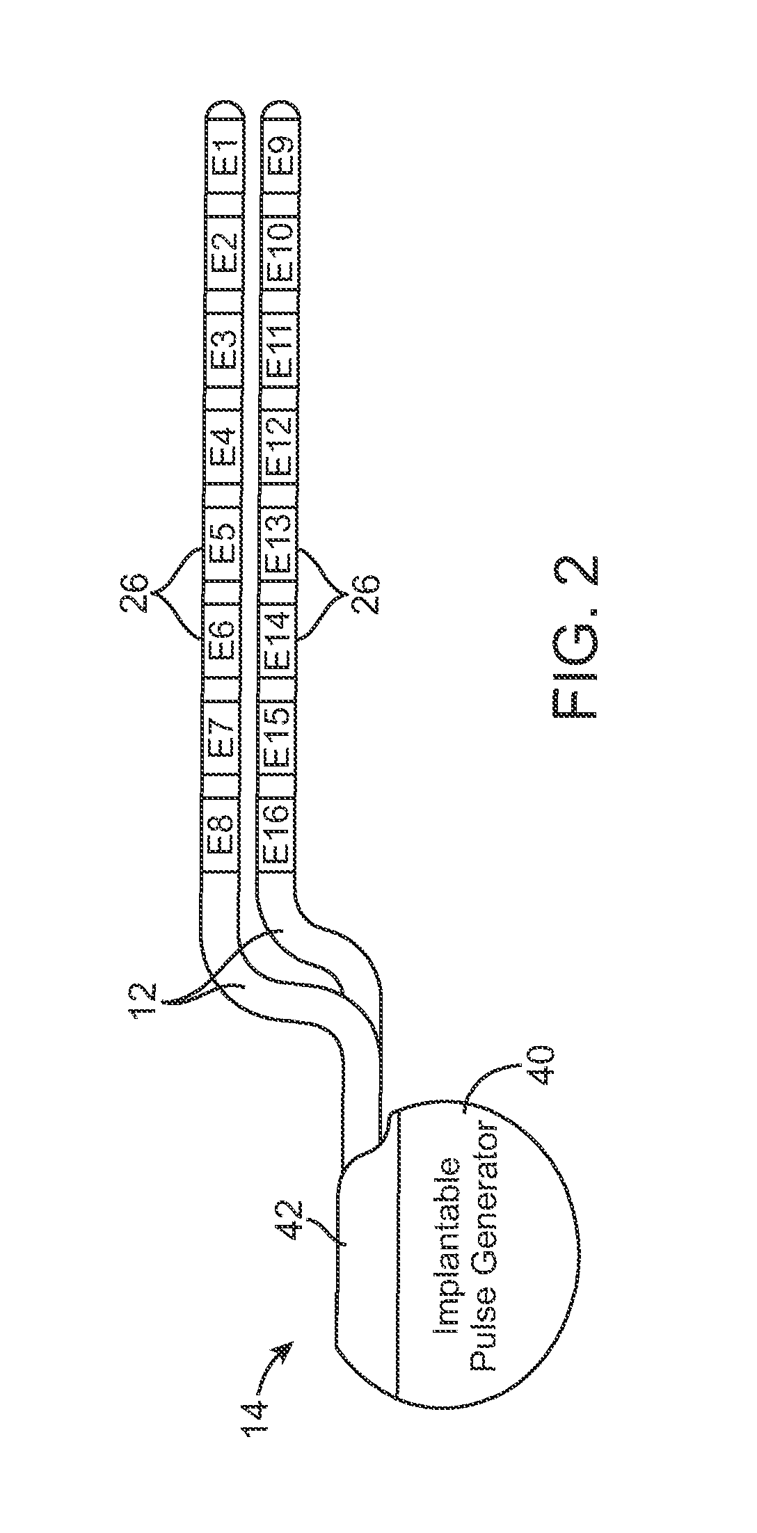
Turning first to FIG. 1, an exemplary spinal cord stimulation (SCS) system 10 generally includes one or more (in this case, two) implantable stimulation leads 12, a pulse generating device in the form of an implantable pulse genera...


PUM


Abstract

In one technique, a desired electrical current distribution on at least three active electrodes is selected. An electrical energy perturbation is generated on at least one electrode. A current-to-voltage relationship at each active electrode is estimated based on the energy perturbation. The current-to-voltage relationship for each active electrode takes into account current flow through other active electrodes. The voltage distribution necessary to achieve the desired current distribution is determined based on the estimated current-to-voltage relationship. Voltage-regulated energy is conveyed between the electrodes and tissue in accordance with the determined electrical voltage distribution. In another technique, an electrical energy perturbation on at least one of the electrodes is generated. Network resistances for each of at least three active electrodes are computed in response to the energy perturbation. The network resistances represent the resistances between the electrodes and common node to which the electrodes are connected.

Description

FIELD OF THE INVENTIONThe present invention relates to tissue stimulation systems, and more particularly, to a system and method for stimulating neural fibers.BACKGROUND OF THE INVENTIONImplantable neurostimulation systems have proven therapeutic in a wide variety of diseases and disorders. Pacemakers and Implantable Cardiac Defibrillators (ICDs) have proven highly effective in the treatment of a number of cardiac conditions (e.g., arrhythmias). Spinal Cord Stimulation (SCS) systems have long been accepted as a therapeutic modality for the treatment of chronic pain syndromes, and the application of tissue stimulation has begun to expand to additional applications such as angina pectoralis and incontinence. Deep Brain Stimulation (DBS) has also been applied therapeutically for well over a decade for the treatment of refractory chronic pain syndromes, and DBS has also recently been applied in additional areas such as movement disorders and epilepsy. Further, in recent investigations, ...

Claims


Application Information

Patent Timeline
Patent Type & Authority Patents(United States)
IPC IPC(8): A61N1/00
CPCA61N1/36071A61N1/0551
Inventor MOFFITT, MICHAELPETERSON, DAVID K. L.
Owner BOSTON SCI NEUROMODULATION CORP
Why Eureka
Try Eureka