Wellbore fluid redistribution and fluid disposal in wellbore environments

a technology of wellbore environment and fluid redistribution, which is applied in the direction of fluid removal, wellbore/well accessories, sealing/packing, etc., can solve the problems of insufficient production of water from the formation, affecting gas desorption, and inhibiting the flow of gas out of the coal seam, so as to reduce the cost of regulation and facilitate the circulation of fluids. , the effect of reducing the cos

Inactive Publication Date: 2011-11-15
BIG CAT ENERGY CORP
View PDF7 Cites 2 Cited by
  • Summary
  • Abstract
  • Description
  • Claims
  • Application Information

AI Technical Summary

Benefits of technology

[0021]One object of the present invention may be to address and perhaps avoid discharging water produced by coal bed methane wells to the surface. Still another object of the invention may be to address compliance with water discharge rules. Another object of the invention may be to address and minimize regulatory costs associated with redistributing water produced by coal bed methane wells. Yet a further object of the invention may be to redistribute water from one geologic section to another, or from multiple geologic sections to another, such as from one aquifer or a plurality of aquifers to another aquifer. An additional object of the invention may be to provide a water flood of a geologic section, such as a formation reservoir. Another object of the invention may be to provide for multiple completion sections of a well and to facilitate circulation of a fluid such as water to maintain well conditions as part of the present invention. Still other objects may be to provide for the exchange of seal elements and for the ports of the present invention to allow for the connection with other features of the present invention.

Problems solved by technology

If the intake is set too high in the well, water from the formation may not be sufficiently produced.
If the intake is set too low, water from the formation may not be sufficiently produced and the water may no longer float the coal fractures (keeping them open), possibly negatively affecting gas desorption or possibly inhibiting the flow of gas out of the coal seam.
The quality of the produced water may vary from better than some bottled waters to poor, possibly depending on proximity of the coal bed methane well to the coal aquifer recharge area.
However, water quality problems may occur after the water reaches the surface and travels for any distance.
At some point in the drainage, these salts may begin to accumulate, thus possibly reducing the discharged water quality.
The discharged water may become impaired because the discharged water may acquire salts along its path to tributaries.
This impaired water may ultimately comingle with unimpaired water and may eventually degrade the fresh water supply.
However, the NPDES permit acquisition process may involve significant drawbacks for coal bed methane producers, including the possibility of a substantial time and financial investment for the producer in obtaining the permit and the possibility of a denial of the permit.
However, traditional re-injection methods may not have been economically viable to re-inject a high volume of produced water from a large number of wells.
The drilling costs of each well may detract from economic viability of traditional re-injection methods.
Furthermore, some formations may already contain a substantial amount of water, thus requiring large pump pressures to exceed the fracture rate of these formations in order to inject the additional waters.
Traditional re-injection methods, furthermore, may be cost prohibitive given surface equipment and processes required.
However, facility and treatment costs may be prohibitively expensive.
Other traditional re-injection techniques involve drilling an additional well or wells near an existing coal bed methane well for re-injection into a shallow aquifer system, but again these attempts may not have been economically viable due to the added costs of the additional wells as well as equipment and pumping costs to reinject the water back into the formations.
Yet other attempts have involved using the produced water for irrigation, but the expenses involved in irrigation (for example, the capital outlay for an irrigation system and the treatment of soils to prevent souring) may have been so high as to be economically unsustainable.
Still attempts may have involved the use of large leach-fields to dispose of water, but it may have been that relatively low permeability soils such as tight clay soils hindered the percolation process.
However, this technique may be dependent on certain pressure ranges to work properly and may perhaps require a time cycle controller to switch a valve when water reaches a set height or time.
The technologies of the above referenced patents and other similar technologies may also be limited in application to brine water disposal for oil and gas reservoirs and not particularly addressing the complexities of redistribution of fresh water into a fresh water system or the corresponding environment.
Furthermore, the complexities associated generally with oil and gas reservoirs and traditional production equipment may actually lead those in the field away from thoughts of more efficient and less mechanically complex techniques, and particularly given the differences in the production environment.
Accordingly, a need may exist to avoid the NPDES permit system altogether, thus possibly streamlining the permit procedure and potentially reducing costs.
Secondary and tertiary recovery is the recovery of oil or gas, or combinations thereof, in production-depleted reservoirs exhibiting low pressure or low flow rates, such that production is not economical or too much gas or water is present.
For example, if there is no readily available source of CO2 near the production facility (miscible displacement), it may be that a CO2 flood may not be economically viable.
Such surface facilities may ultimately increase the operating cost of the field, perhaps reducing the economic viability of the operation.
Those skilled in the art may not have fully appreciated the nature of the problems and challenges involved.
As a result, attempts to meet these needs may not have effectively solved one or more of the problems or challenges here identified.

Method used


Image

  • Wellbore fluid redistribution and fluid disposal in wellbore environments
  • Wellbore fluid redistribution and fluid disposal in wellbore environments
  • Wellbore fluid redistribution and fluid disposal in wellbore environments

Examples


Embodiment Construction

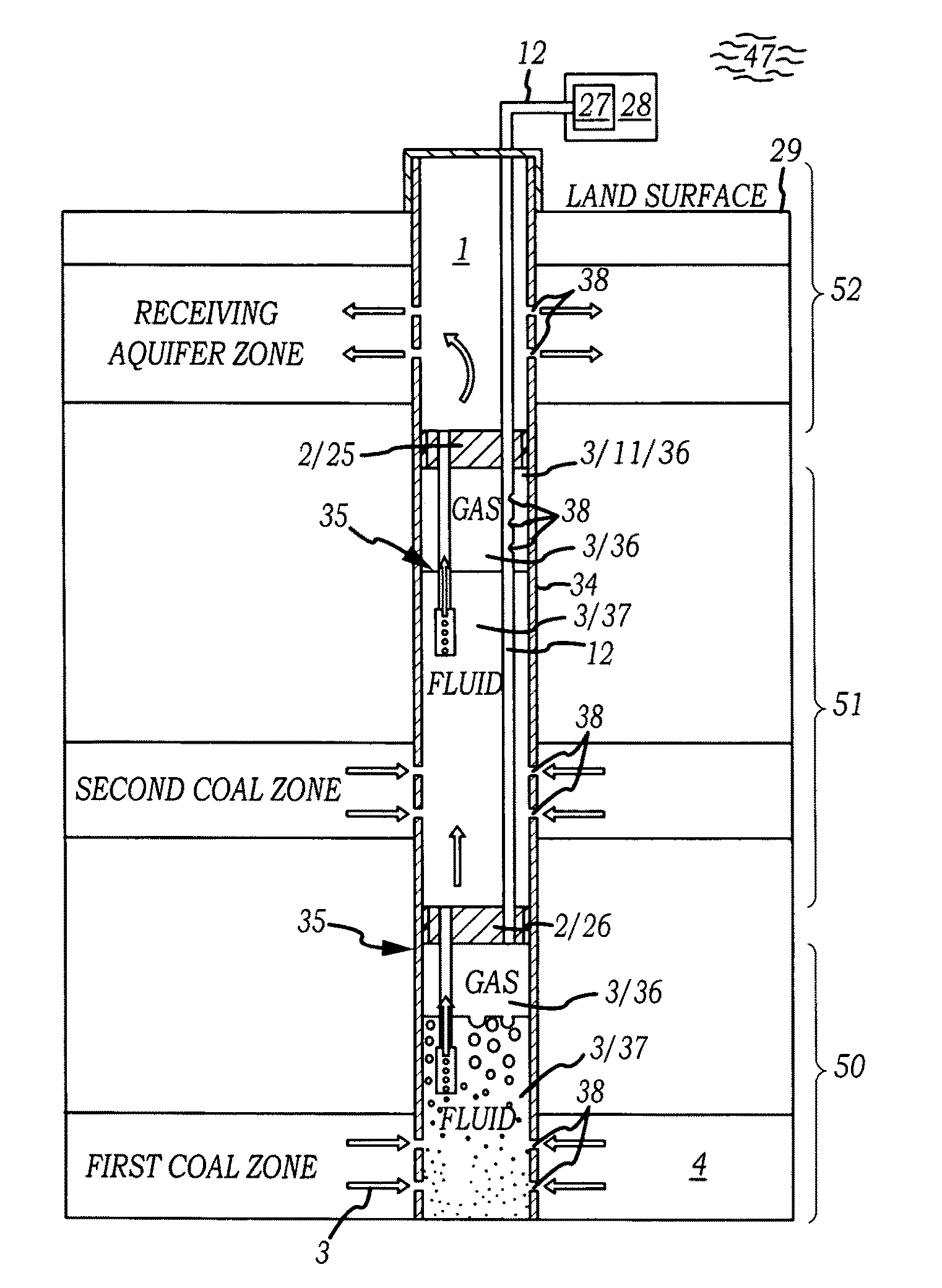
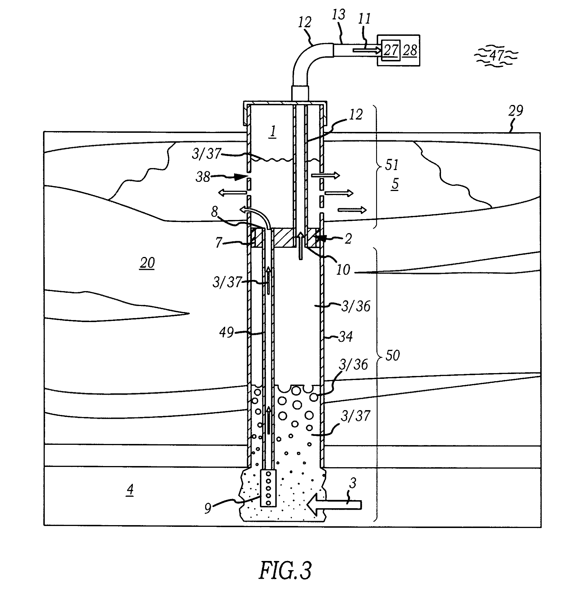
[0034]Generally, devices and methods of redistribution of fluids produced in well bore environments. Specifically, well bore fluid redistribution apparatuses which can isolate and redistribute fluids produced in well bores between geologic sections to reduce surface discharge of certain portions of the fluids.

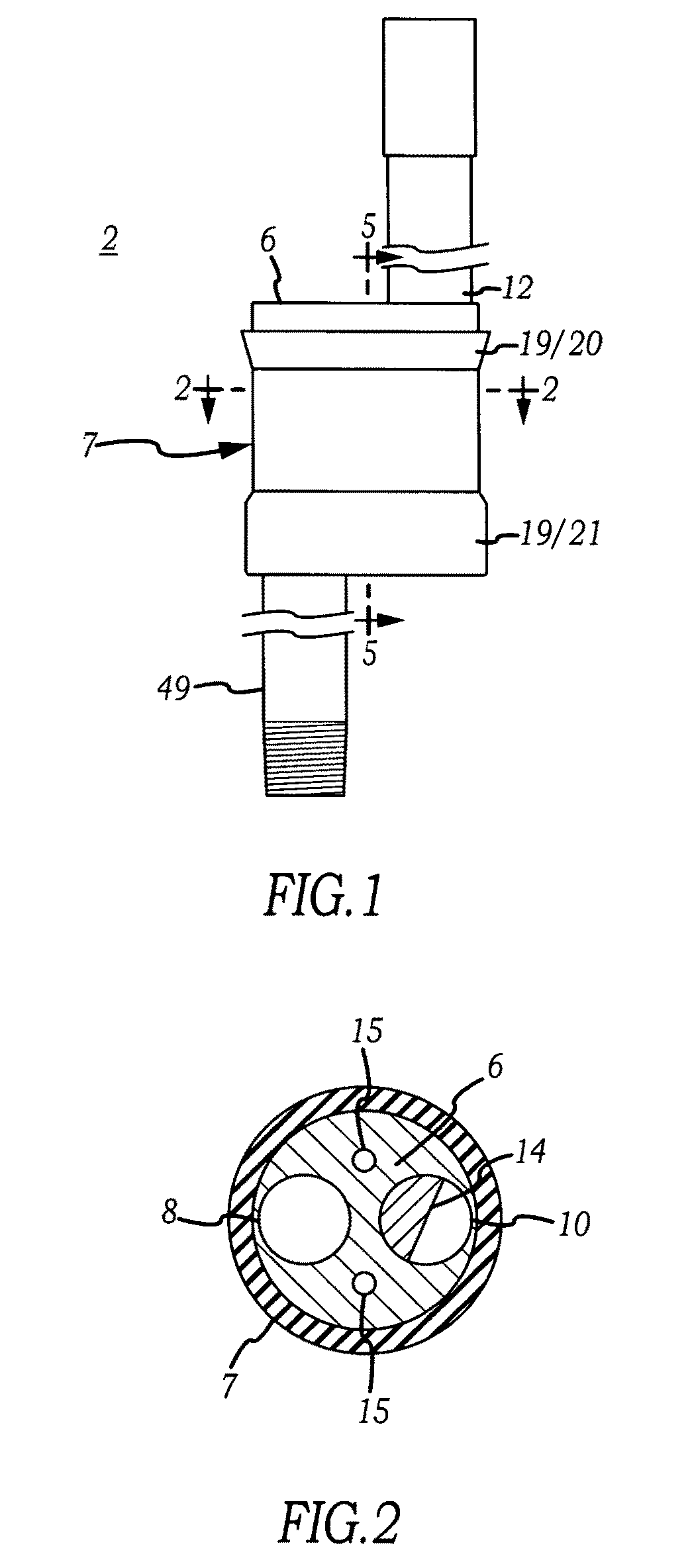
[0035]Now referring primarily to FIGS. 1, 2 and 3, certain embodiments of a well bore fluid redistribution apparatus (2) (also referred to as the “apparatus”) are shown which can be located in a well bore (1) (see example in FIG. 3). The external surface of the well bore fluid redistribution apparatus (2) can sufficiently circumferentially engage a corresponding part of the well bore (1) (or the well bore casing (34)) to isolate fluid (3) on either side of the apparatus (2). The fluid (3) isolated on either side of the apparatus (2) can be redistributed within the well bore (2) or redistributed between a first geologic section (4) and a second geologic section (5) (or more geol...


PUM


Abstract

Generally, devices and methods of redistribution of fluids produced in well bore environments. Specifically, well bore fluid redistribution apparatuses which can isolate and redistribute fluids produced in well bores between geologic sections to reduce surface discharge of fluids.

Description

[0001]This United States patent application is a continuation-in-part of U.S. patent application Ser. No. 11 / 399,793, filed Apr. 5, 2006, which claims the benefit of U.S. Provisional Patent Application No. 60 / 668,896, filed Apr. 5, 2005, each hereby incorporated by reference herein.I. TECHNICAL FIELD[0002]Generally, devices and methods of redistribution of fluids produced in well bore environments. Specifically, well bore fluid redistribution apparatuses which can isolate and redistribute fluids produced in well bores between geologic sections to reduce surface discharge of fluids.II. BACKGROUND[0003]Methane gas may be produced in the mining of coal. Coal formations naturally produce methane gas. For example, methane gas may be produced by dewatering activities of the mining process. Methane gas that is contained in the coal formation may be biogenic (generated by biologic organisms) or organic (generated by organic decomposition of coal) origin.[0004]Recovery of the methane gas pre...

Claims


Application Information

Patent Timeline
Patent Type & Authority Patents(United States)
IPC IPC(8): E21B43/14
CPCE21B43/006E21B43/385
Inventor MURPHY, RAYMOND P.BARRITT, TIMOTHY G.STOCKDALE, RICHARD G.
Owner BIG CAT ENERGY CORP
Why Eureka
Try Eureka