Exhaust-gas purification device disposition structure of vehicle

a technology of exhaust gas purification device and disposition structure, which is applied in the direction of machines/engines, mechanical equipment, transportation and packaging, etc., can solve the problems of deoxidizer leaking from the broken tank entering the vehicle compartment, bad situation, and ammonia toxicity and strong irritant odor

Inactive Publication Date: 2011-11-15
MAZDA MOTOR CORP
View PDF63 Cites 18 Cited by
  • Summary
  • Abstract
  • Description
  • Claims
  • Application Information

AI Technical Summary

Benefits of technology

[0009]The present invention has been devised in view of the above-described matters, and an object of the present invention is to prevent surely the deoxidizer from entering into the vehicle compartment even in case of the breakage of the deoxidizer tank, and avoid the mistake of supplying the wrong liquid into the wrong supply (pouring) port tank which may be made by confusing the ports.

Problems solved by technology

Meanwhile, as well known, the ammonia has some toxicity and strong irritant odor.
In the conventional layout, however, the deoxidizer tank is disposed above the vehicle-body floor, so that there is a concern that the deoxidizer leaking from the broken tank would enter into the vehicle compartment.
Accordingly, in a case where the deoxidizer tank is disposed in the engine room, the leaking urea water solution tends to be resolved easily so as to produce the ammonia, resulting in a bad situation.
Further, there is another concern that in case of supplying the deoxidizer into the deoxidizer tank, the fuel into a fuel supply port which opens to the outside of the vehicle compartment, a wiper washer liquid into a pouring port which opens to the inside of the engine room, or the like, the wrong liquid would be supplied into the wrong port by mistake, for example, the fuel or the washer liquid are poured into the supply port of the deoxidization tank with confusion of the ports.

Method used


Image

  • Exhaust-gas purification device disposition structure of vehicle
  • Exhaust-gas purification device disposition structure of vehicle
  • Exhaust-gas purification device disposition structure of vehicle

Examples


Embodiment Construction

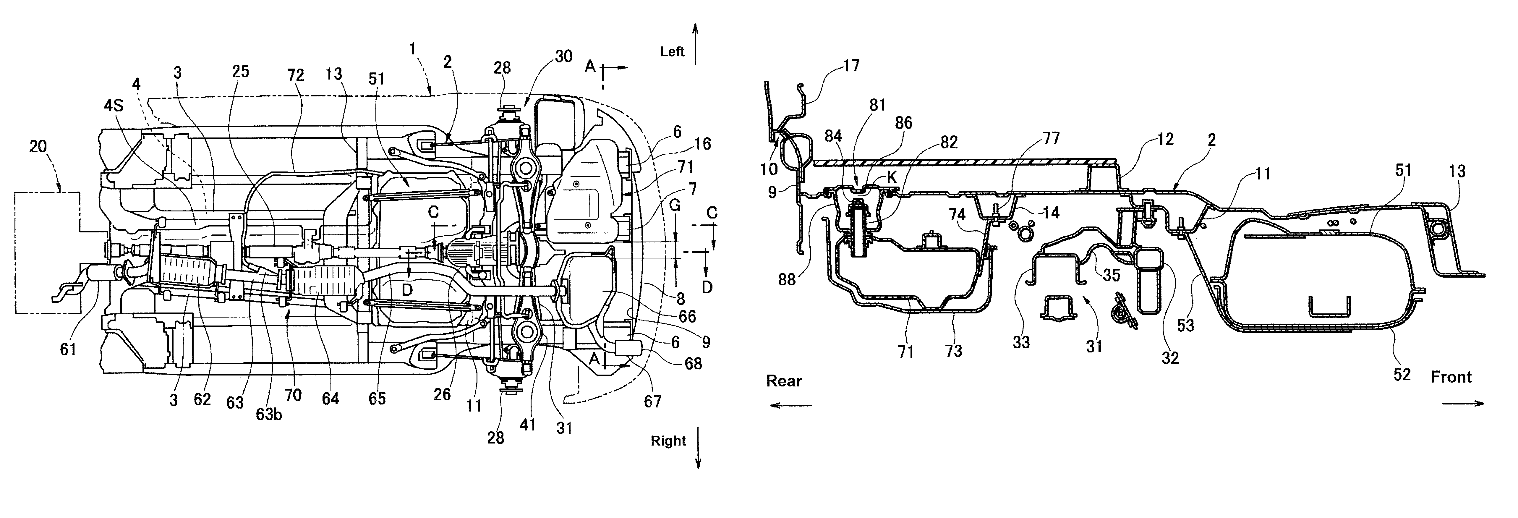
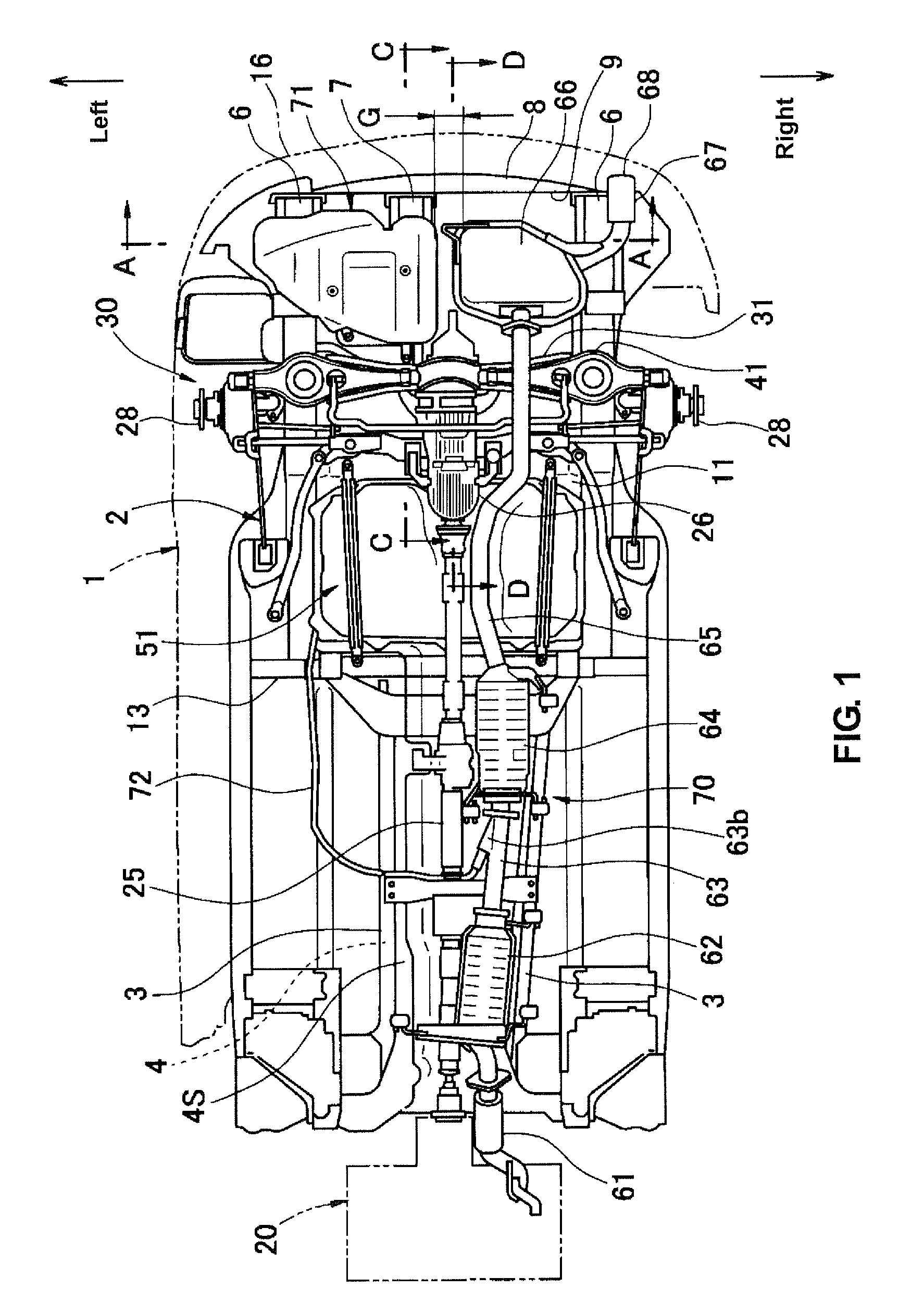
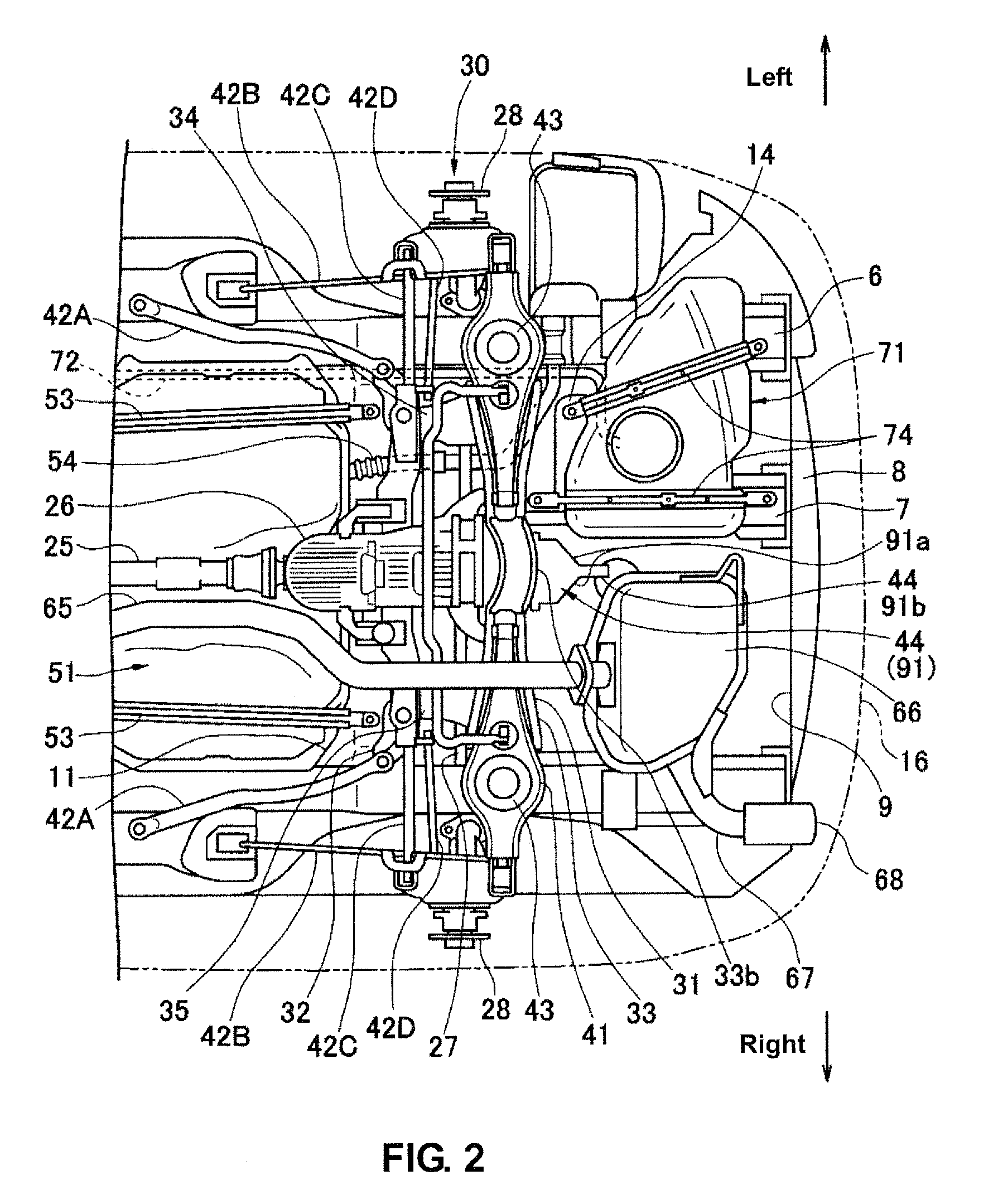
[0044]Hereinafter, a preferred embodiment of the present invention will be described referring to the accompanying drawings. FIG. 1 is a bottom view (seen from below) of a floor of a vehicle compartment of an automotive vehicle equipped with an exhaust-gas purification device according an embodiment of the present invention. FIG. 2 is a partially-enlarged bottom view of a vehicle rear portion of FIG. 1. FIG. 3 is a plan view of the floor at the vehicle rear portion. FIG. 4 is a sectional view taken along line A-A of FIG. 1. FIG. 5 is a partial sectional view taken along line B-B of FIG. 3. FIG. 6 is a partial sectional view taken along line C-C of FIG. 1. FIG. 7 is a sectional view taken along line D-D of FIG. 1.

[0045]As apparent from FIG. 1, an automotive vehicle according to the present embodiment comprises a power transmission system from an engine unit 20 to a rear differential gear 26 and an engine exhaust system which extends from the engine unit 20 to a vehicle rear end, whic...


PUM


Abstract

An exhaust-gas purification device disposition structure of a vehicle, comprises a fuel tank with a fuel supply port which is disposed so as to be open to an outside of a vehicle compartment, and a urea tank to accommodate urea water solution as deoxidizer to purify exhaust gas. The urea tank is disposed outside the vehicle compartment, and a pouring port of the urea tank is provided inside the vehicle compartment. Accordingly, the urea water solution can be surely prevented from entering into the vehicle compartment even in case of the breakage of the urea tank, and the mistake of supplying the wrong liquid into the wrong supply (pouring) port tank which may be made by confusing the ports can be avoided.

Description

BACKGROUND OF THE INVENTION[0001]The present invention relates to a disposition structure of an exhaust-gas purification device to purify exhaust gas from an internal combustion engine of a vehicle by using deoxidizer.[0002]It is generally known that the nitrogen oxide (NOx) contained in the exhaust gas from the internal combustion engine (diesel engine, gasoline engine, etc.) of vehicles, such as an automotive vehicle, is purified by a NOx deoxidizing catalyst which is disposed in an engine exhaust pipe.[0003]It has been recently proposed that the ammonia is used as the deoxidizer for improving the purification efficiency by the NOx deoxidizing catalyst. For example, if the urea water solution, as the deoxidizer, is added into the exhaust pipe upstream of the deoxidizing catalyst, the added urea water solution is heated and resolved by the exhaust gas of the engine, resulting in producing ammonia. This ammonia acts as the deoxidizer so that the purification of NOx in the exhaust ga...

Claims


Application Information

Patent Timeline
Patent Type & Authority Patents(United States)
IPC IPC(8): B60K13/04F01N3/00
CPCF01N13/1822B60K15/063F01N3/2066F01N2340/04F01N2610/1406B60K13/04Y02A50/20
Inventor IKEGAMI, MAKOTOSHIMADA, YUKIICHIROUSAKIYAMA, NORITAKASAHASHI, NORIYOSHIMATSUE, KOTAISHIHARA, CHIKARAMATSUMOTO, SHINYANISHIMURA, YOSHIKAZUMURAKAMI, YOSHIAKITANAKA, MASAMITSUUEKI, KEN
Owner MAZDA MOTOR CORP
Why Eureka
Try Eureka