Perpendicular magnetic recording head with a laminated pole

a perpendicular magnetic recording and laminated pole technology, applied in the field of main pole layer of pmr writers, can solve the problems of head-induced data erasure, poor magnetic remanence, and still suffer from pmr problems, so as to reduce remanence, reduce remanence, and minimize the effect of pole erasur

Active Publication Date: 2011-11-15
HEADWAY TECH INC
View PDF12 Cites 2 Cited by
  • Summary
  • Abstract
  • Description
  • Claims
  • Application Information

AI Technical Summary

Benefits of technology

[0016]One objective of the present invention is to provide a laminated main pole layer with high moment material that provides good overwrite performance, and has a design that reduces remanence so that pole erasure is minimized in PMR writer applications.
[0017]Another objective of the present invention is to provide a laminated main pole layer according to the first objective while providing a means to improve signal to noise ratio.

Problems solved by technology

However, PMR still suffers some problems.
One of the biggest issues is the head-induced data erasure that is of particular concern since the erasure occurs after writing.
However, magnetic remanence is not improved.
One disadvantage of prior art AFC lamination schemes is that the coupling strength of a FeCo / Ru / FeCo configuration or the like is typically large and this type of AFC lamination will inevitably cause a large anisotropy field and low magnetic moment under a low field.

Method used


Image

  • Perpendicular magnetic recording head with a laminated pole
  • Perpendicular magnetic recording head with a laminated pole
  • Perpendicular magnetic recording head with a laminated pole

Examples


first embodiment

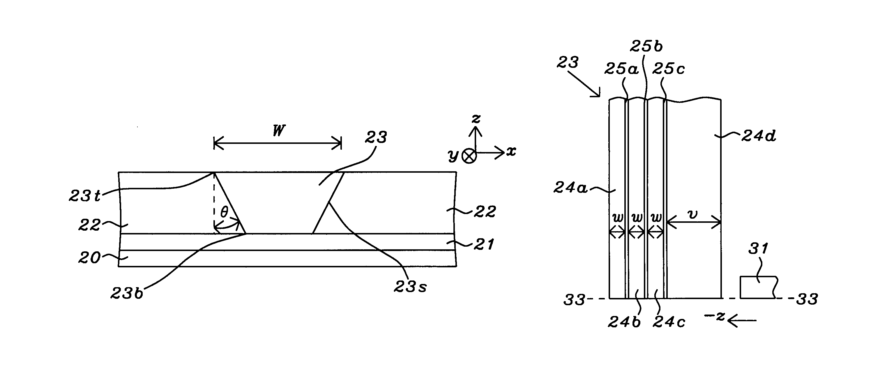
[0051]Referring to FIG. 8b, an enlarged view of a portion of the write pole 23 in FIG. 8a is shown on the RIE resistant layer 21. In a first embodiment, the laminated write pole 23 is comprised of alternating magnetic layers 24a-24d and non-magnetic spacers 25a-25c. An important feature is that the trailing magnetic layer 24d has a thickness greater than that of the other magnetic layers 24a-24c and preferably has a thickness that comprises ≧25% of the total thickness of the magnetic layers in the write pole 23. Optionally, when the trailing magnetic layer 24d has a concave shape (not shown) with a curved trailing edge, the volume of the trailing magnetic layer is greater than the volume of other magnetic layers 24a-24c and is preferably ≧25% of the total volume of the magnetic layers 24a-24d. The present invention also encompasses other embodiments wherein the number of magnetic layers is unequal to 4 but is an integer greater than 1. Moreover, there may be a cap layer (not shown) ...

second embodiment

[0054]Referring to FIG. 9b, a second embodiment is shown in which magnetic layers 24a-24c have a thickness less than v for the trailing magnetic layer 24d. Moreover, the thickness of the magnetic layers becomes progressively smaller as the distance from magnetic layer 24d increases. For example, the thicknesses a, b, and c, for magnetic layers 24a, 24b, and 24c, respectively, have values such that c>b>a. Optionally, for examples where there is a plurality of “n” magnetic layers, the “n−1” layers other than the trailing magnetic layer may each have different thicknesses that become progressively smaller with increasing distance from the trailing magnetic layer. The “n−1” non-magnetic spacers that separate the “n” magnetic layers may have an equivalent thickness or their thicknesses may vary within a range of 5 to 100 Angstroms.

[0055]Referring to FIG. 9c, a third embodiment of the present invention is illustrated in which a non-magnetic spacer between the trailing magnetic layer 24d a...


PUM

PropertyMeasurementUnit
thicknessaaaaaaaaaa
thicknessaaaaaaaaaa
heightaaaaaaaaaa

Abstract

A laminated write pole layer for a PMR write head is disclosed in which a plurality of “n” magnetic layers and “n−1” non-magnetic spacers are formed in an alternating fashion on a substrate. The non-magnetic spacers promote exchange decoupling or antiferromagnetic coupling between adjacent magnetic layers. Writability is improved when the trailing magnetic layer has a thickness greater than the thickness of other magnetic layers and preferably >25% of the total thickness of the magnetic layers. The thicknesses of the other magnetic layers may be equal or may become progressively smaller with increasing distance from the trailing magnetic layer. In another embodiment, the non-magnetic spacer between the trailing magnetic layer and the nearest magnetic layer is replaced by a magnetic spacer made of a soft magnetic material to promote magnetic coupling and effectively increase the thickness of the trailing magnetic layer.

Description

RELATED PATENT APPLICATIONS[0001]This application is related to Ser. No. 11 / 825,034, filing date Jul. 3, 2007; and Ser. No. 11 / 820,962, filing date Jun. 21, 2007; both assigned to the same assignee as the current invention and which are herein incorporated by reference in its entirety.FIELD OF THE INVENTION[0002]The invention relates to a main pole layer of a PMR writer and a method for making the same wherein the main pole layer is a laminate of a magnetic material and a non-magnetic spacer to improve overwrite performance, minimize data erasure after a write operation, and improve signal to noise ratio.BACKGROUND OF THE INVENTION[0003]Perpendicular magnetic recording (PMR) has become the mainstream technology for disk drive applications beyond 200 Gbit / in2, replacing longitudinal magnetic recording (LMR) devices. Due to the continuing reduction of transducer size, high moment soft magnetic thin films with a Bs above 22 kG are required for write head applications. A PMR head which ...

Claims


Application Information

Patent Timeline
Patent Type & Authority Patents(United States)
IPC IPC(8): G11B5/147G11B5/127
CPCG11B5/1278G11B5/147G11B5/3116G11B5/3143
Inventor TAKANO, KENICHIGUAN, LIJIEZHOU, YUCHENSMYTH, JOEDOVEK, MORIS
Owner HEADWAY TECH INC
Why Eureka
Try Eureka