
Achromatic and uncoupled medical gantry

a chromatic and uncoupled technology, applied in the field of cancer treatment, can solve the problems of significant beam intensity loss and/or continuous beam tuning, release of much of the energy, and disrupting the molecules of healthy tissue and organs

Active Publication Date: 2011-11-22
BROOKHAVEN SCI ASSOCS
View PDF10 Cites 29 Cited by
  • Summary
  • Abstract
  • Description
  • Claims
  • Application Information

AI Technical Summary

Benefits of technology

The present invention provides a particle beam gantry for delivering a particle beam to a patient that maintains the beam's linearity and achromaticity (uncoupling) at the exit of the gantry, regardless of the gantry's rotation. The gantry includes a plurality of dipole magnets and quadrupole magnets that bend the beam path and focus it to a small point on the patient. The gantry can be rotated by any angle between 0 and 360 degrees, and the strength and location of the magnets are determined to achieve the desired achromatic and uncoupled conditions. The invention also includes a method for delivering a particle beam to a patient through the gantry. The technical effects of the invention include improved beam accuracy and stability, as well as improved patient safety and treatment efficacy.

Problems solved by technology

However, X-rays release much of their energy quickly after penetrating the skin, disrupting the molecules of healthy tissue and organs.
The disadvantage of such a gantry arrangement, however, that if the non-symmetric ion beam (i.e., a beam having different emittances in vertical and horizontal planes) is introduced into the gantry from a fixed transfer line, the beam transport within the gantry arrangement of Cole et al. becomes dependent on the angle of gantry rotation, which means that the patient will not receive the same high-precision beam spot from every direction.
Naturally the drawback of using such a device is a significant beam intensity loss and / or continuous beam tuning, which may require additional unnecessary time during the irradiation of the patient.
However, the disadvantage of the Benedikt et al. system is that it occupies about 10 m of extra length of the transfer line and requires an extra equipment for extremely precise mechanical rotation, which is a significant drawback for design of compact medical accelerator complexes appropriate for use in the hospital facilities.
Nonetheless, the drawback of such a system is that the beam at the entrance of the gantry must be constrained to have the same angular divergence or size in the horizontal and vertical planes, which requires additional system to control the beam itself.

Method used


Image

  • Achromatic and uncoupled medical gantry
  • Achromatic and uncoupled medical gantry
  • Achromatic and uncoupled medical gantry

Examples


example 1

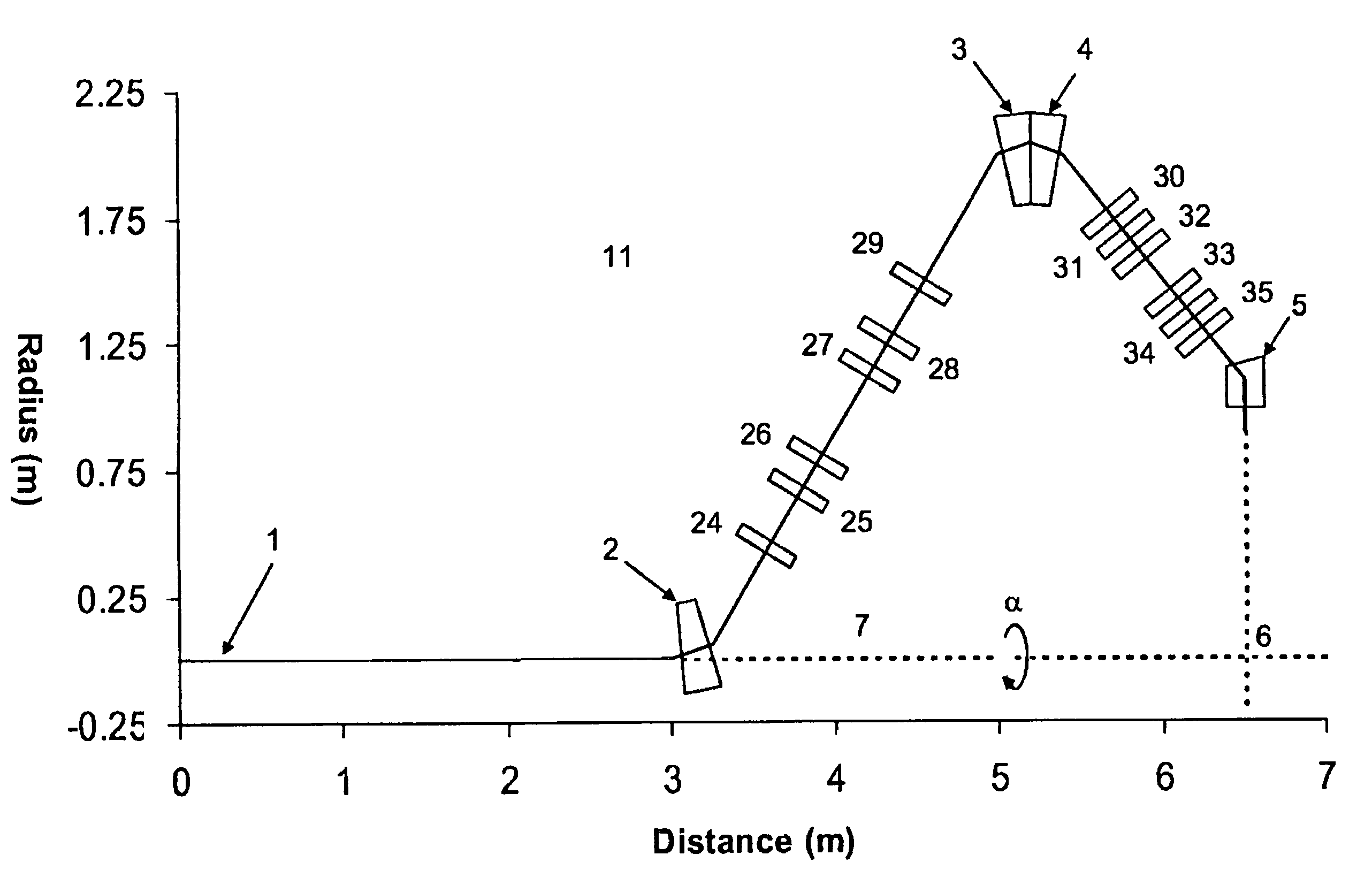
[0076]The simulation of the gantry setup used two dipoles, i.e., 2 and 3, as shown in FIGS. 3 and 5, each bending the beam by 20° but in opposite directions, and 3 pairs of quadrupoles, i.e., 24-29, symmetrically placed about the center between the dipoles. For the simulation purposes, the gantry was then rotated by an angle α=22.5° about the beam axis. The parameters of the magnets and the drift spaces for the first half of the first section of the gantry are summarized in Table 1.

[0077]

TABLE 1Parameters of the elements for half of the six quadrupoleand seven-quadrupole linesSix QuadrupolesSeven QuadrupolesElementρ [m]αρ [m]αDIPOLE0.520°0.520°ElementL [m]k [m−2]L [m]k [m−2]DRIFT0.1—0.1—QUAD0.15 36.8490.15 29.7744DRIFT0.3334—0.3—QUAD0.15−20.84980.15−18.8317DRIFT0.30106—0.724—QUAD0.15 10.6700.15 13.7085DRIFT1.1905—0.72574—½ QUAD——0.075−27.4169

[0078]FIG. 8 shows the beta functions βx, βy, and dispersion functions ηx, and ηy functions, plotted along the first section of the gantry, i.e...

example 2

[0082]In order to provide additional control on the βx βy functions, an additional quadrupole, e.g., quadrupole 30 in FIGS. 4 and 6, was introduced into the setup presented in Example 1, which was placed at the center of the line to preserve the symmetry. The gantry in FIGS. 4 and 6 is also separated in two sections as in Example 1, with the difference from example 1 being that the first section, i.e., between dipoles 2 and 3, contains 7 quadrupoles. The inclusion of the 7th quadrupole (30) which was placed at the center of the line to preserve symmetry, provides additional control on the beta functions βx, βy. The parameters of the magnets and the drift spaces for the first half of the seven-quadrupoles section of the line, are summarized in Table 1. FIG. 9 shows the beta functions βx, βy, and dispersion functions ηx, ηy, plotted along the first section of the gantry. The values of these functions were calculated by the computer code MAD used in the “couple” mode, with the gantry r...

example 3

[0086]In order to examine achromaticity and coupling control along the entire gantry, the computer simulation was ran with the setup shown in FIG. 6, however, unlike Examples 1 and 2, dipoles 3 and 4 were considered as one dipole and the gantry was not separated into two sections. FIG. 10 shows the beta functions βx, βy, and the dispersion functions ηx, ηy, plotted along the line as calculated using the computer code MAD in the “coupled” mode. The above discussed conditions for the rotation of the medical gantry satisfy the particle beam line to be achromatic and uncoupled over the entire gantry.


PUM


Abstract

A medical gantry that focus the beam from the beginning of the gantry to the exit of the gantry independent of the rotation angle of the gantry by keeping the beam achromatic and uncoupled, thus, avoiding the use of collimators or rotators, or additional equipment to control the beam divergence, which may cause beam intensity loss or additional time in irradiation of the patient, or disadvantageously increase the overall gantry size inapplicable for the use in the medical treatment facility.

Description

[0001]This invention was made with Government support under contract number DE-AC02-98CH10886, awarded by the U.S. Department of Energy. The Government has certain rights in the invention.BACKGROUND OF THE INVENTION[0002]I. Field of the Invention[0003]This invention relates generally to a cancer therapy and, more particularly, to a medical particle delivery system having an achromatic and uncoupled gantry design.[0004]II. Background of the Related Art[0005]In traditional radiation therapy, X-ray beams are typically used to treat cancer. However, X-rays release much of their energy quickly after penetrating the skin, disrupting the molecules of healthy tissue and organs. Protons, neutron, α-ray or other ion rays, on the other hand, have excellent physical properties for radiation therapy which permit one to control very precisely the shape of the dose distribution inside the patient's body. The dose delivered by such an ion ray beam is well localized in space, not only in the lateral...

Claims


Application Information

Patent Timeline
Patent Type & Authority Patents(United States)
IPC IPC(8): H01J29/02
CPCA61N5/10A61N5/1081H05H7/04A61N2005/1087
Inventor TSOUPAS, NICHOLAOSKAYRAN, DMITRYLITVINENKO, VLADIMIRMACKAY, WILLIAM W.
Owner BROOKHAVEN SCI ASSOCS
Learn More