RAID system and method compatible with improved drive select

a drive select and drive technology, applied in the direction of input/output to record carriers, redundancy hardware error correction, instruments, etc., can solve the problems of system vulnerability, system raid system difficulty, and relatively complex system of microprocessors and/or data buffers, etc., to achieve the effect of improving performan

Inactive Publication Date: 2011-11-22
SEAGATE TECH LLC
View PDF10 Cites 17 Cited by
  • Summary
  • Abstract
  • Description
  • Claims
  • Application Information

AI Technical Summary

Benefits of technology

[0014]Some embodiments of the present invention involve the recognition of opportunities for performance enhancement which are presented by the presence of two (or more) copies of at least some data on a multi-disk system, such as a RAID system. In one embodiment, disk rotation latency can be reduced, on average, based on the recognition that, if corresponding data is not always precisely in rotational phase between two or more disks, the rotational latency for one or the other of the disks will be less than the (average) rotational latency for data on a single disk. In one embodiment, defect tables are mirrored between the two (or more) disks of a RAID system, so that it is possible to maintain the disks such that corresponding data is always in a fixed phase relationship (such as 180 degrees out of phase) between the disks. In one embodiment, rotational phase of one or more of the disks of a system are periodically or randomly changed to avoid disks being maintained substantially in-phase for sustained periods of time.
[0015]Embodiments of the present invention also include the recognition that, in addition to a potential for reducing rotational latency, the presence of two or more copies of data on different disks also presents an opportunity for reducing head positional latency (“seek time”). In general, unless drives are specifically controlled to avoid this situation, when there is a desire to read (or write) data which reside on target tracks on first and second disks (which may be the same tracks or different tracks, on the two disks), the time required to position the head over the target track of one disk will be different from the time required to position the head over the target track of the second disk. In one embodiment of the invention, head positioning for a read is performed on all disks of the RAID system (which contain the target data) and the data is returned to the host by reading the data from the first disk ready. In one embodiment of the invention, this procedure also involves an abort of the seek and / or read operation on other disks of the system, e.g., to avoid having the system wait for completion of the operation by all disks (and thus, potentially, losing some, or all, of the time advantage potentially available from a “first disk ready” operation). In at least one embodiment, in order to achieve an abort which is sufficiently rapid (i.e., which aborts the seek or read operation on drives, other than the first drive ready, with sufficient rapidity that, on average, head positioning latency is reduced, compared to a non-RAID system), the abort is performed at a hardware level, e.g., without requiring execution of driver software (such as a host driver). In one embodiment of the invention, head position latency is reduced by predicting which head will reach the target track first and sending the read (or, in some cases, write) command only to that disk. In one embodiment, head prediction is performed using disk drive logic, preferably involving back channel communication of head prediction information. In one embodiment, disk drives are controlled in such a manner that average head positions on the two disks are non-random (on average). For example, by controlling disk drives such that a first drive head spends more than half its time over tracks with addresses in the upper half of the address range and the other drive head spends more than half its time over tracks with addresses in the lower half of the address range, at least some head positioning latency improvement can be achieved by sending data transfer requests with addresses in the upper half of the address range to the first disk and sending data transfer requests with addresses in the lower half of the address range to the second disk.
[0017]In order for at least some of the RAID functions to be performed, it is generally necessary to provide for duplication of at least some, and preferably substantially all, data among the two or more disks of a RAID system. According to one aspect of the invention, the mirroring process is delayed, e.g., by a predetermined or user selected period, either for substantially all data, or, in some embodiments, for selected types or sources of data. One use of such delay is to provide a period of time in which data can be scanned for the presence of, e.g., a virus, thus, potentially avoiding a situation where a virus infects both disks (in a two disk RAID system) of a RAID system. In one embodiment, a list is formed of the address blocks for data which is written to a first drive and not immediately mirrored on a second drive. In this way, re-mirroring can be performed by copying data from all locations on such lists, to the second drive. In one embodiment, such re-mirroring is performed by transferring data from one drive to another using a back channel. In some situations, it may be desired to copy substantially all files from one of the drives onto another drive of the RAID system. Examples include when one of the drives of the system has been replaced or when a RAID system is implemented on a multi-drive system for the first time, or after a period of suspension of RAID functionality. In one embodiment of the invention, such copying of substantially all of the contents of one disk to another, is performed in a rapid manner by avoiding the need for transferring the data to a host computer, and thence to the second drive, as part of the copying process. In one embodiment, avoidance of transfer to and from the host computer is achieved by using a back channel data pathway for some or all such data transfer.
[0019]In one embodiment of the present invention, the RAID system is configured to physically fit one (or more) disk drives into a relatively small space such as a 5.25 inch form factor, a 3.5 inch form factor, or a CD ROM form factor. A 3.5 inch form factor has a width of 3.5 inches (8.9 centimeters) and a height of 1 inch (2.5 cm). A 5.25 inch form factor has a width of 5.25 inches (13.3 cm) and a height of (8.9 centimeters), 1.5 inches (3.2 cm) for a half-high drive. A 5.25 drive bay has a width of 5.75 inches (14.6 cm), a depth of 8 inches (20.3 cm) and a height of 1.63 inches (4 cm). A 3.5 drive bay has a width of 4 inches (10 cm), a depth of 5.75 inches (14.6 cm) and a height of 1 inch (2.5 cm). A “half-high” bay generally refers to a bay with a height of 1.63 inches (4 cm). The CD ROM form factor is substantially the same as a 5.25 inch form factor. In some embodiments, some or all of the drives of a multi-drive system are configured to accommodate user removability. In one embodiment, the drive is provided with a rail or similar system for guiding drives into, or out of, position. In some embodiments, drives are substantially covered with, or otherwise provided with, a shock resistant covering or material. In some embodiments, a locking door is provided, e.g., to restrict access to a removable drive. In some embodiments, data encryption is provided to protect against unauthorized use of a drive removed from a system. In some embodiments, a system is configured to discourage positioning of the drives in other than an orientation with a plane of the drives substantially vertical, e.g., to assist in avoiding shock or other mechanical damage to removed disk drives.
[0020]In one embodiment, one or more disks of the disk drive are provided in an external “box” or housing substantially separate from the desktop computer housing, and connected thereto by, e.g., USB, Firewire, Ethernet or wireless data paths. In one embodiment, such external box is provided with vents or other openings and / or with a disk drive orientation (e.g., substantially vertical) to provide a convective or “chimney effect” air flow to at least partially assist in drive cooling, preferably so as to reduce or eliminate the need for potentially noisy cooling fans. In various embodiments, drives in such an external box can be either substantially fixed or user-removable.
[0022]In at least one embodiment of the invention, a RAID system is provided which can be implemented as a hardware RAID system, while avoiding certain shortcomings of previous RAID systems. It can be implemented without the need for occupying a PCI slot, so as to fit within a standard drive form factor. The system can provide automatic failover and can continue to operate even after a failure of a boot sector. Disk drives of the system, either in a PC chassis, or an external box, can be provided as non-removable or user-removable. Mirroring delay or hold-off can avoid virus infection or other problems. RAID control circuitry is, preferably, on a card directly coupled to two or more drives using rigid connectors and / or flex connectors. RAID control is preferably provided without processors or buffers. The presence of two or more copies of data is exploited to enhance performance. Read errors can be repaired on-the-fly or in a disk scan process.

Problems solved by technology

At least some previous approaches have used relatively complex systems of microprocessors and / or data buffers for performing operations such as drive select, or other RAID functions.
Such systems can be vulnerable, however, if the host device operating system fails to “boot” on one of the drives of the RAID system.
This is believed to be a difficulty with software RAID systems, even though “boot files” may reside on both disks of a RAID system.
Until such manual resynchronization is performed, there is a risk that an error in the second disk of the RAID system could render some data irretrievably lost.
This procedure can be undesirably slow.
Relatively long path lengths can undesirably degrade signal quality, particularly in the case of high speed data transfer rates.

Method used


Image

  • RAID system and method compatible with improved drive select
  • RAID system and method compatible with improved drive select
  • RAID system and method compatible with improved drive select

Examples


Embodiment Construction

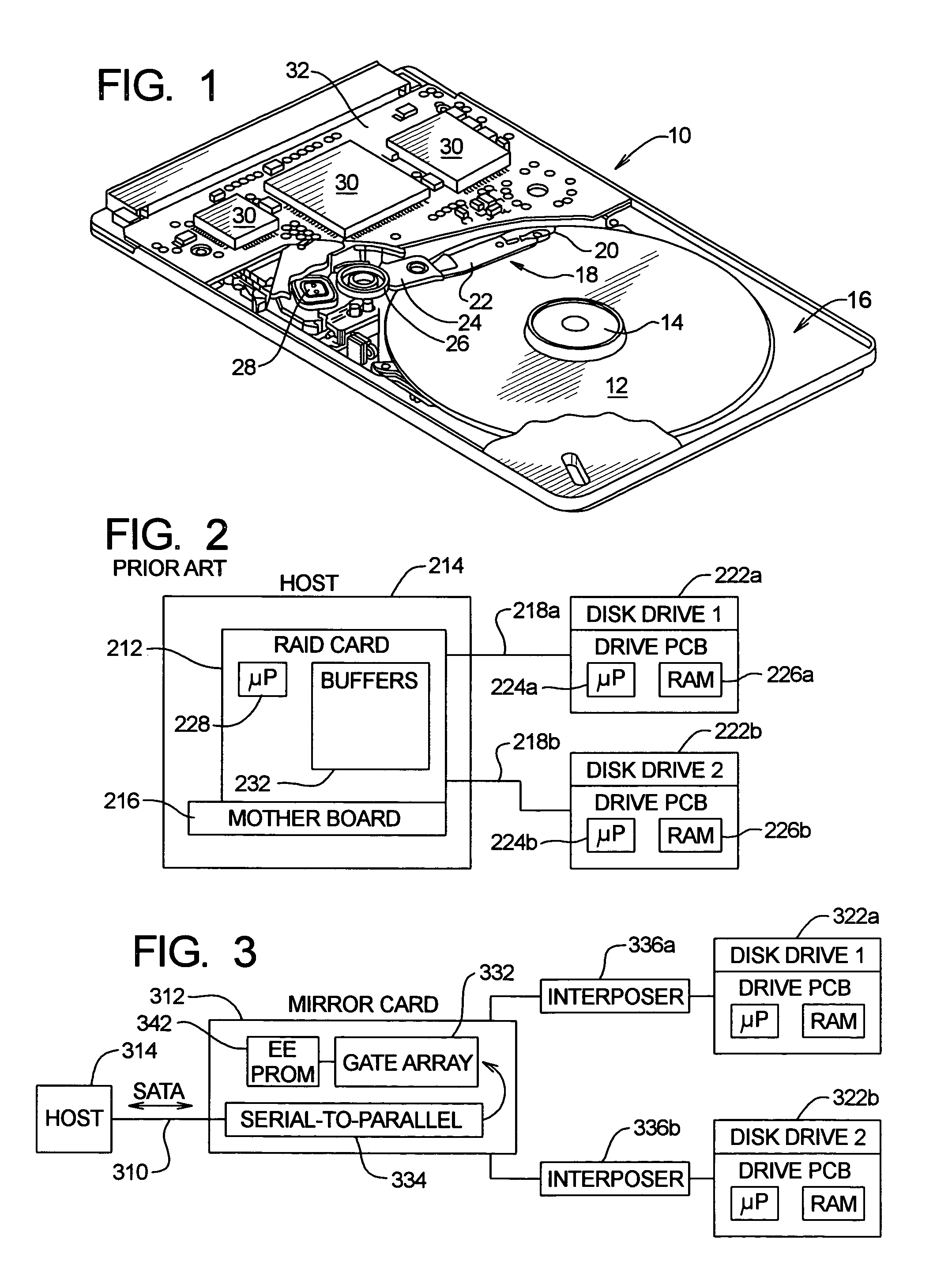
[0085]Data storage devices including, e.g., those normally provided as part of, or in connection with, a computer or other electronic device, can be of various types. In one general category, data is stored on a fixed or rotating (or otherwise movable) data storage medium and a read head, a write head and / or a read / write head is positioned adjacent desired locations of the medium for writing data thereto or reading data therefrom. One common example of a data storage device of this type is a disk drive (often called a “hard” disk or “fixed” disk drive). Although many concepts and aspects pertaining to the present invention will be described herein in the context of a disk drive, those with skill in the art, after understanding the present disclosure, will appreciate that the advantages provided by the present invention are not necessarily limited to disk drives.

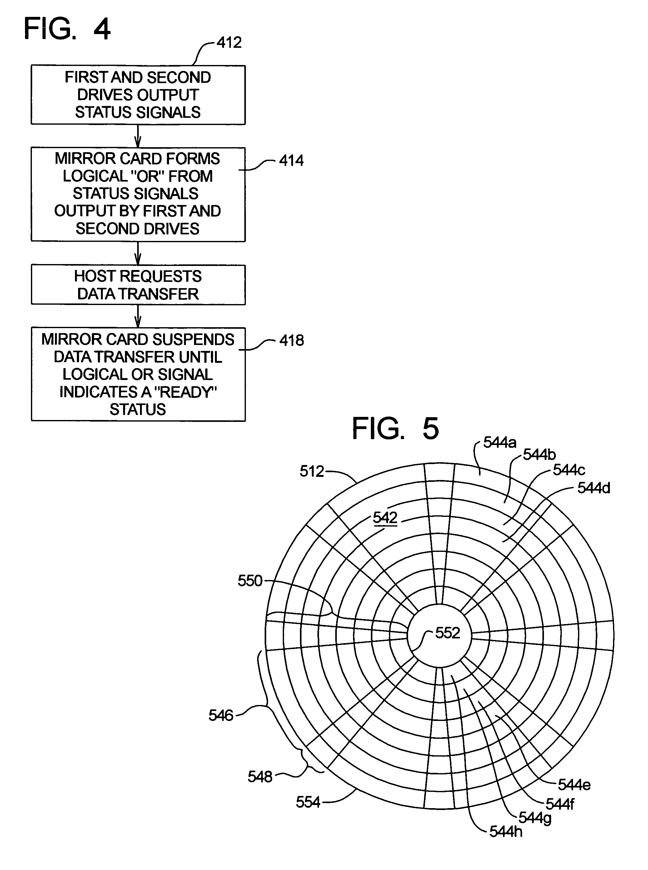
[0086]Computer disk drives store information on magnetic disks. Typically, the information is stored on each disk in concen...


PUM


Abstract

A RAID system is provided which can be implemented as a hardware RAID system while avoiding certain shortcomings of previous RAID systems. The RAID system makes it possible to avoid or reduce the number of buffers or processors and can take advantage of drive logic to achieve RAID functions or enhancements. RAID functionality can be provided in a manner to accommodate one or more ATA drive interfaces. To avoid drive replacement problems, host requests for drive serial numbers are responded to with a mirror serial number. In one embodiment, the read address is used to select which drive will perform a read operation.

Description

TECHNICAL FIELD[0001]The present invention is directed to multiple data storage devices (such as disk drives), particularly with improvements which may include, e.g., drive select, internal and / or external mounting and content copying, error correction and / or performance enhancement, back channel-facilitated operations, and the like.BACKGROUND INFORMATION[0002]In many contexts, it is useful to provide partial or full redundancy for stored data. Although the present invention is not necessarily limited to disk drives, in the context of disk drives, data redundancy is sometimes described or provided as one of various types of RAID (redundant array of inexpensive drives) systems. In one such system, each disk drive has a corresponding “mirror” drive and operations are coordinated such that all, or substantially all, data written to one drive is also written to the other. Many previous RAID systems were provided primarily for purposes of data integrity, such that if some or all data was...

Claims


Application Information

Patent Timeline
Patent Type & Authority Patents(United States)
IPC IPC(8): G06F12/00
CPCG06F3/0611G06F3/0659G06F3/0689G06F11/2023
Inventor HILLER, BERNHARDALEXOPOULOS, PANTELISBRUNNETT, DONBUDDHAVARAM, CHANDRACHATARD, THIERRYCHEW, DAVIDDUELL, SAMUEL R.GRIFFITHS, JEFFHERNANDEZ, JOHANNAKIMBALL, ROBERT L.KVAMME, ERICLEACH, LEROYLEE, MICHAELMCGRATH, JAMESFITZGERALD, LEGAL REPRESENTATIVE, KATHLEENMILBY, ROBERTSCHARDT, BRUCESCHLUMBERGER, MAURICESCHRECK, ERHARDSONNENFELD, RICHARD
Owner SEAGATE TECH LLC
Why Eureka
Try Eureka