
Agricultural bagger with dual rotor and/or variable-taper tunnel

a technology of variable-taper tunnel and bagger, which is applied in the field of agricultural baggers, can solve the problems of high risk of being sucked through and shredded by the primary compression mechanism, high risk of being sucked through and shredded, and the feed in the upper bag is only moderately compacted, so as to improve the flow of agricultural feed and increase the compaction

Inactive Publication Date: 2011-11-29
WINGERT PAUL R
View PDF94 Cites 10 Cited by
  • Summary
  • Abstract
  • Description
  • Claims
  • Application Information

AI Technical Summary

Benefits of technology

The solution effectively prevents feed bridging, ensures even compaction throughout the bag, and allows for efficient filling of large amounts of feed while enhancing safety by reducing the motivation to manually unclog the hopper.

Problems solved by technology

One contends with numerous problems in using previous bagging structures.
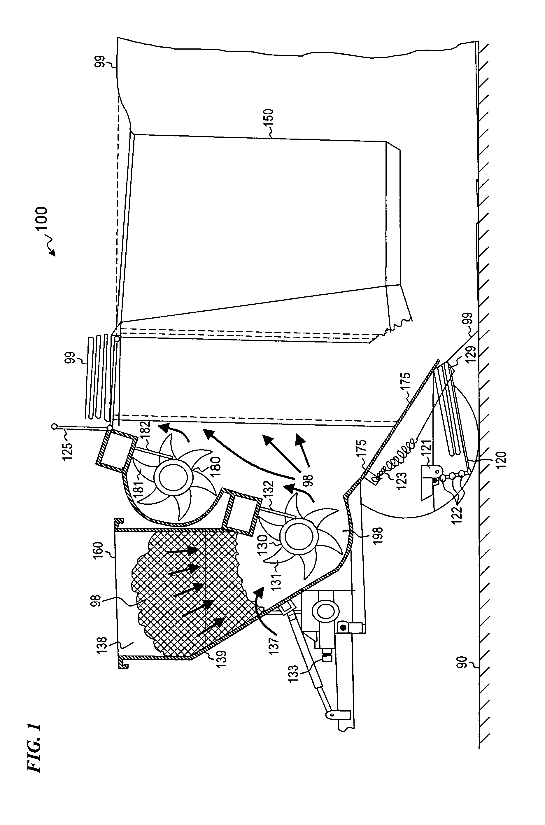
For example, there is a safety problem caused by feed that bridges within the tapered input hopper.
Persons may be tempted to unclog the hopper by stomping or otherwise inserting an arm or a leg thus risking being sucked through and shredded by the primary compression mechanism.
Conventional baggers also suffer from an inability to adequately compact feed in the upper and lower portions of the tunnel, thus leaving the feed in the lower bag highly compacted and the feed in the upper bag only moderately compacted.
Conventional baggers also suffer from inability to efficiently force large amounts of feed into the bag while providing a variable control on the tunnel opening to control the amount of feed compaction.

Method used


Image

  • Agricultural bagger with dual rotor and/or variable-taper tunnel
  • Agricultural bagger with dual rotor and/or variable-taper tunnel
  • Agricultural bagger with dual rotor and/or variable-taper tunnel

Examples


Embodiment Construction

[0030]Although the following detailed description contains many specifics for the purpose of illustration, a person of ordinary skill in the art will appreciate that many variations and alterations to the following details are within the scope of the invention. Accordingly, the following preferred embodiments of the invention are set forth without any loss of generality to, and without imposing limitations upon the claimed invention.

[0031]In the following detailed description of the preferred embodiments, reference is made to the accompanying drawings that form a part hereof, and in which are shown by way of illustration specific embodiments in which the invention may be practiced. It is understood that other embodiments may be utilized and structural changes may be made without departing from the scope of the present invention.

[0032]The leading digit(s) of reference numbers appearing in the Figures generally corresponds to the Figure number in which that component is first introduc...


PUM

PropertyMeasurementUnit
diameteraaaaaaaaaa
diameteraaaaaaaaaa
diameteraaaaaaaaaa

Abstract

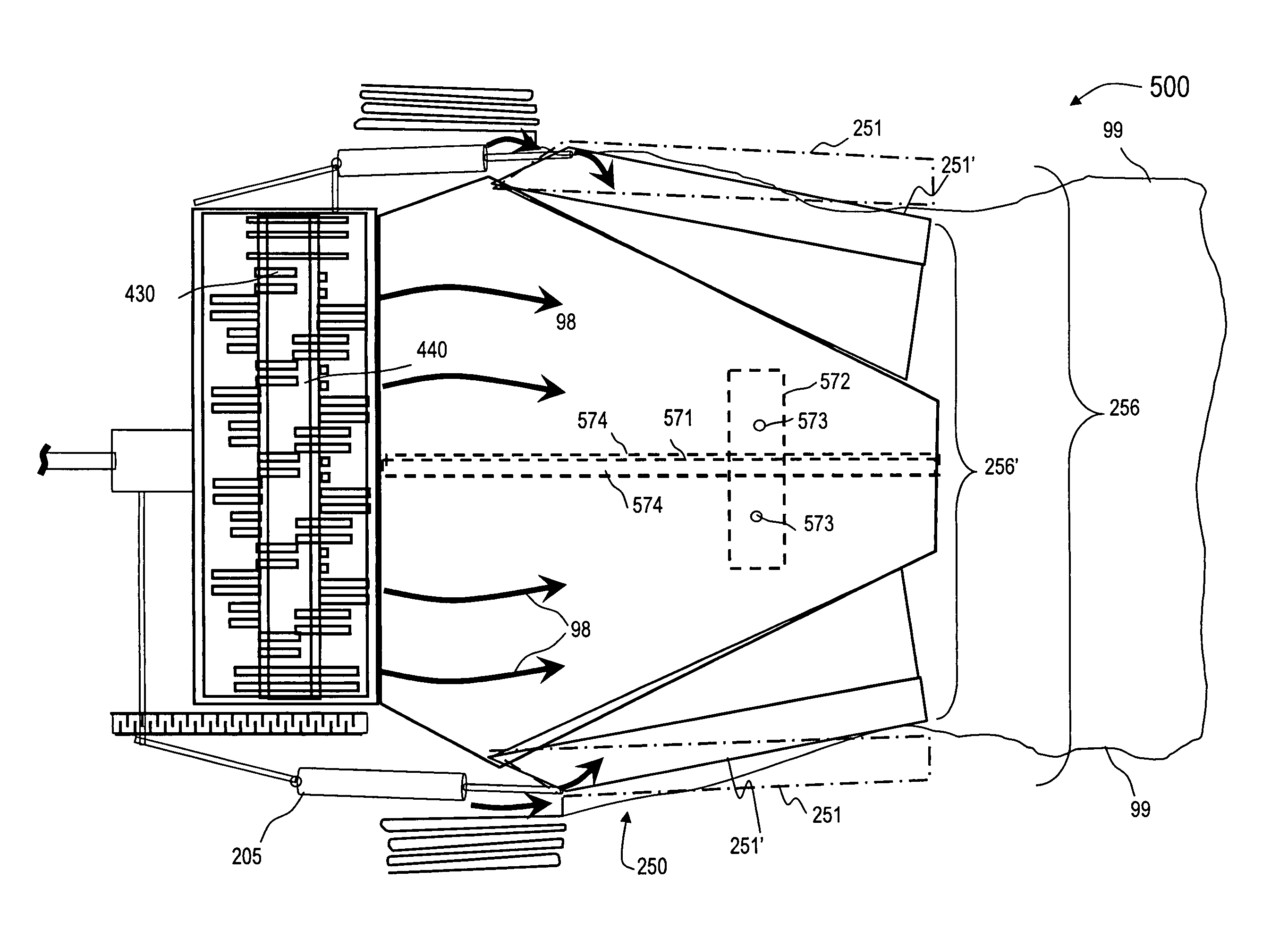
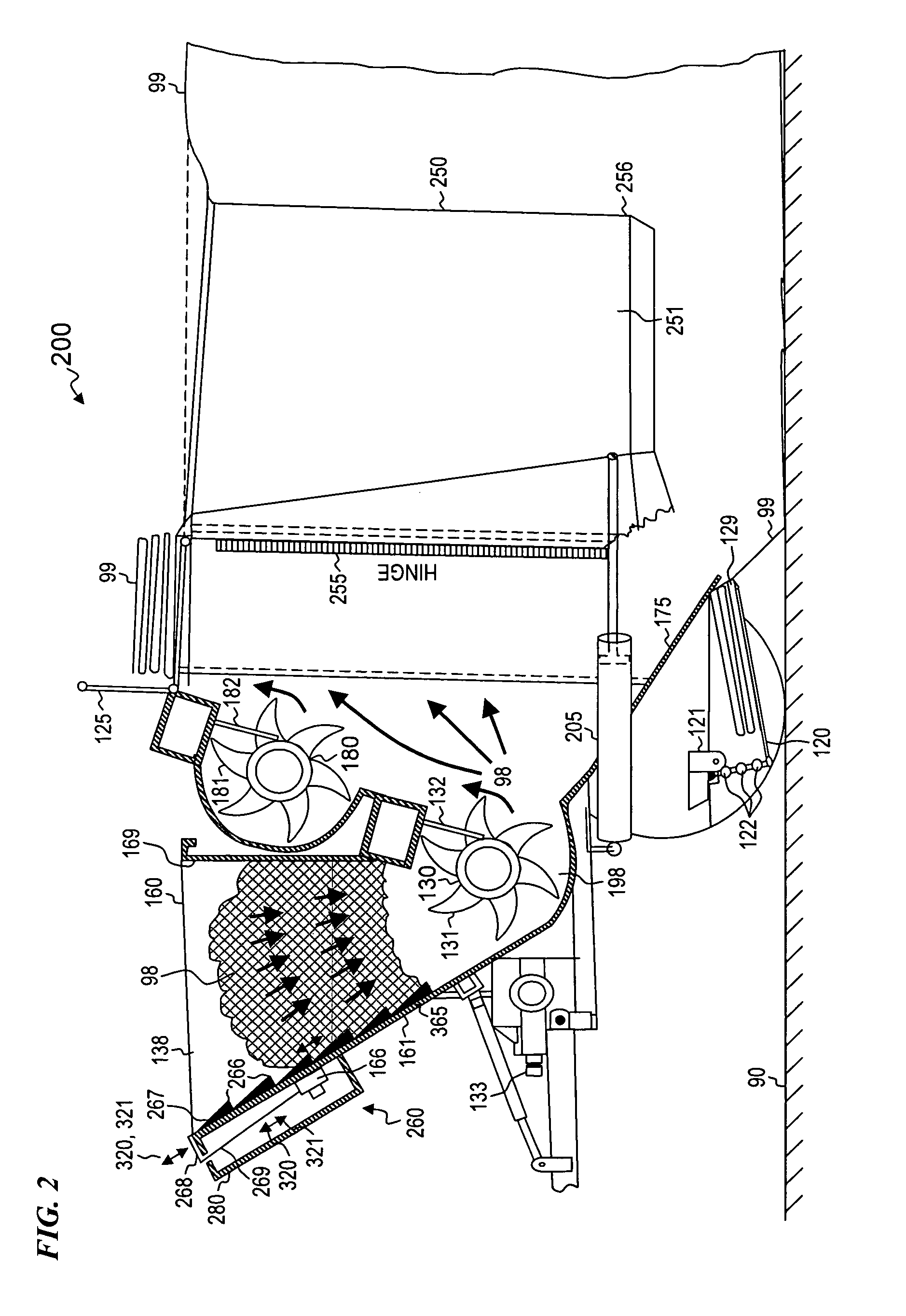
An agricultural bagger apparatus and method for compacting feed into a horizontally deployed bag including a moving hopper wall and mechanism for moving the wall at an input end of hopper. The wall moving mechanism and the moving wall of the hopper sweeps the feed adjacent to the sloping wall to prevent feed bridging. A safety enclosure isolates the wall moving mechanism from contaminants and prevents exposure to the wall moving mechanism. Some embodiments also compact feed in the upper portion of a tunnel, for example, by reciprocating a hinged piston above a primary compression mechanism. A tunnel-adjustment mechanism varies a cross-section area of the tunnel exit in order to control the amount of compaction on the feed as it leaves the tunnel and enters the bag. In some embodiments, dual counter-rotating toothed compression mechanism force feed between the rotors and into the tunnel at a rate and pressure greater than what is possible with only one multiple-toothed compressor rotor.

Description

CROSS-REFERENCE TO RELATED APPLICATIONS[0001]This application is a continuation of U.S. patent application Ser. No. 11 / 944,599 filed Nov. 23, 2007, which is a continuation of U.S. patent application Ser. No. 11 / 345,059 filed Jan. 31, 2006, which claimed benefit of U.S. Provisional Patent Application No. 60 / 648,833 filed Jan. 31, 2005, each of which is hereby incorporated by reference in its entirety.[0002]This invention also is related to the following six patent applications:[0003]U.S. Ser. No. 08 / 904,160 filed Jul. 31, 1997, now U.S. Pat. No. 5,878,552 issued Mar. 9, 1999 to Paul R. Wingert;[0004]U.S. Ser. No. 09 / 175,821 filed Oct. 20, 1998, now U.S. Pat. No. 6,061,999 issued May 16, 2000 to Paul R. Wingert;[0005]U.S. Ser. No. 09 / 571,424 filed May 15, 2000, now U.S. Pat. No. 6,516,586 issued Feb. 11, 2003 to Paul R. Wingert;[0006]U.S. Ser. No. 09 / 721,268 filed Nov. 22, 2000, now U.S. Pat. No. 6,672,034 issued Jan. 6, 2004 to Paul R. Wingert;[0007]U.S. Ser. No. 09 / 977,036 filed Oct...

Claims


Application Information

Patent Timeline
Patent Type & Authority Patents(United States)
IPC IPC(8): B65B63/02
CPCA01F25/183A01F2025/145B30B9/301
Inventor WINGERT, PAUL R.
Owner WINGERT PAUL R
Learn More