Chuck

a technology of chuck and chuck body, which is applied in the field of chuck, can solve the problems of increasing the wear and damage of the chuck, affecting the performance of the chuck, and affecting the operation of the chuck, so as to reduce the friction loss of sliding, and reduce the surface pressure

Inactive Publication Date: 2011-11-29
HILTI AG
View PDF20 Cites 2 Cited by
  • Summary
  • Abstract
  • Description
  • Claims
  • Application Information

AI Technical Summary

Benefits of technology

[0012]The above-discussed critical axial region, which is susceptible to mechanical breaking, is subjected to noticeably smaller loads so that at a predetermined fatigue strength limit, it is capable to withstand a high torque, without being noticeably damaged. The additional contact lengths of the rotation transmitting webs, which noticeably increase the overall length of the webs, transmit to the working tool jerky tension loads, which are manually applied by the user through the power tool, simultaneously with a high torque, without breaking the elements of the system.
[0014]The greater contact surface results, at standard loads, in a smaller surface pressures, whereby wear is substantially reduced. In addition, the smaller surface pressures leads to smaller sliding friction losses of the shank which is received in the receiving sleeve with a possibility of a limited axial movement. Thereby, the transmission of the impact energy to the working tool is improved.
[0015]Advantageously, the rotation transmitting webs are spaced from a receiving side end of the receiving sleeve by a distance that amounts at most to a half of the guide diameter. Thereby, axial guide lengths of the receiving sleeve, which are not used for the torque transmission, are reduced, which, in turn, reduces the overall length of the chuck.

Problems solved by technology

It has been shown that a drill with a diameter above 17 mm leads to an increase wear and damage of the chuck in particular, to a noticeably high wear of the contact surfaces of the rotation transmitting webs.
In particular, with modern, reinforcement-proof hammer drills, increased occurrences of a working tool blocking in a reinforced bore are observed.
When the user wants to pull the hammer drill out of the bore, high torques are applied to the working tool, and high jerky tension forces are generated which are transmitted to the working tool by the receiving side edge of the receiving opening for the locking member.
These forces lead to breaking of the receiving sleeve in the vicinity of the receiving side edge when these forces exceed the allowable multi-axes tension.

Method used


Image

  • Chuck
  • Chuck

Examples


Embodiment Construction

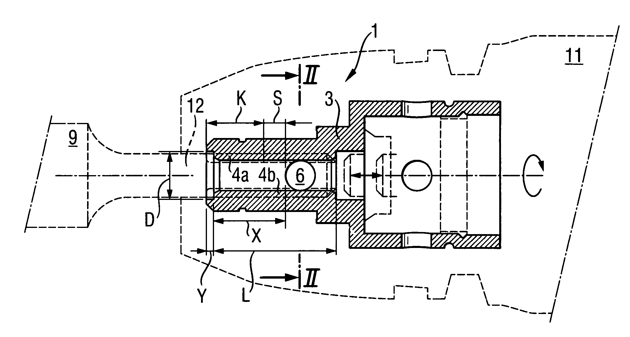
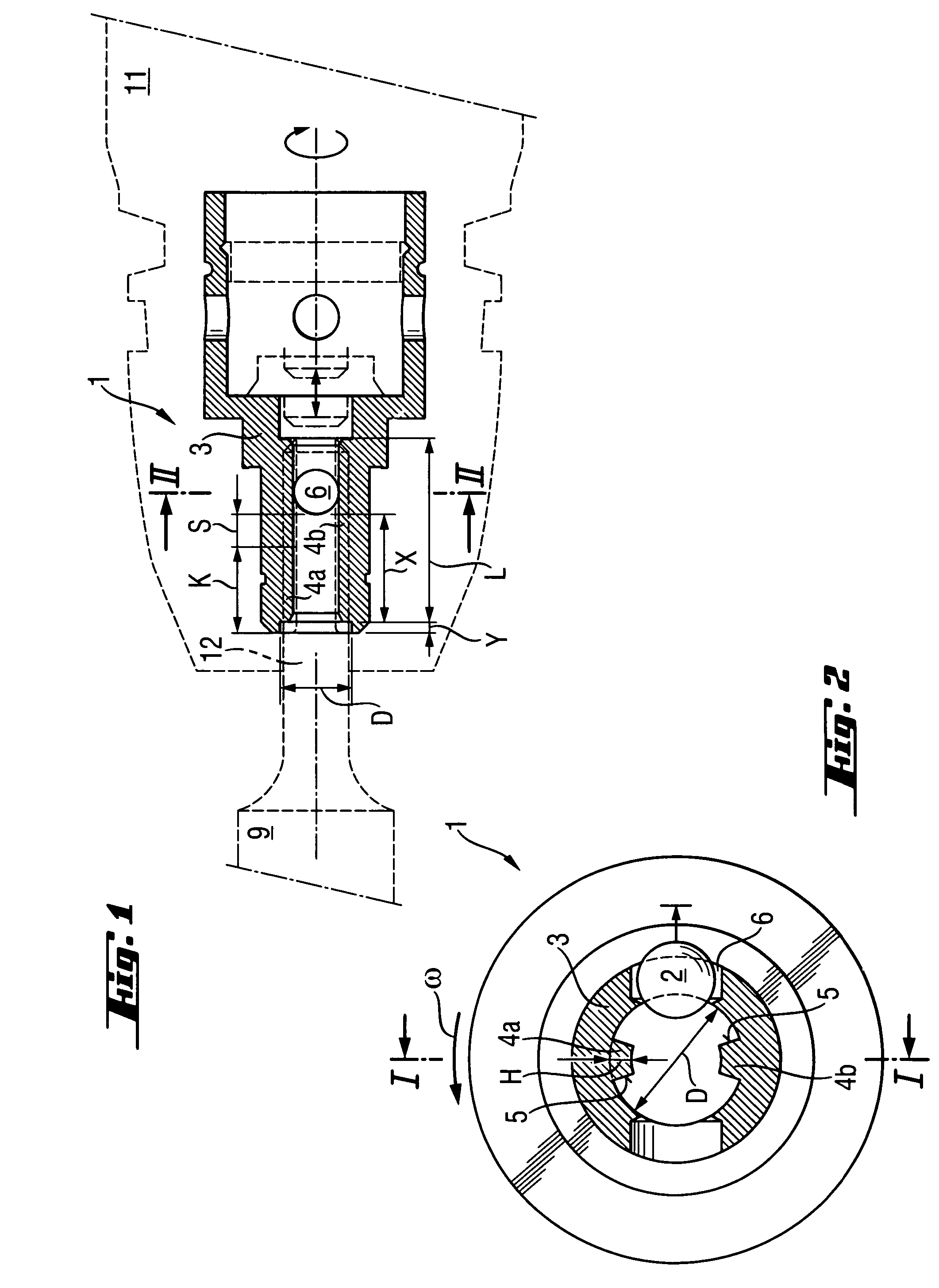
[0021]A chuck 1 of a rotary-percussion power tool 11 for driving a working tool 9, which is shown in FIGS. 1-2, has two strip-shaped, rotation transmitting webs 4a, 4b which project radially inward from a hollow cylindrical receiving sleeve 3 having a guide diameter D, and a locking member 2 in form of a ball radially displaceable through an opening 6 provided in the receiving sleeve 3. The rotation transmitting webs 4a, 4b have a height H−0.15 of the guide diameter D of the receiving sleeve 3 and a length L, and are provided with radially extending contact surfaces 5. The receiving side end of the rotation transmitting webs 4a, 4b is spaced by a distance X from the receiving side edge of the opening 6. The distance X is approximately equal to a double of the guide diameter D. The length L of the rotation transmitting webs 4a, 4b amounts to a triple of the guide diameter. The rotation transmitting webs 4a, 4b are spaced from the receiving side end of the receiving sleeve 3 by a dist...


PUM


Abstract

A chuck includes a hollow cylindrical sleeve (3) having at least two, opposite, rotation transmitting strip-shaped webs (4a, 4b) projecting radially inward, and at least one locking member (2) radially displaceable through a radial opening formed in the receiving sleeve, with the receiving side end of the rotation transmitting webs (4a, 4b) being spaced from a receiving side edge of the radial opening (6) by a distance (X) 1.5 times greater than the guide diameter (D) of the receiving sleeve (3).

Description

BACKGROUND OF INVENTION[0001]1. Field of Invention[0002]The present invention relates to a chuck with a radially displaceable locking member, in particular, for a hammer drill for receiving a percussion drill.[0003]2. Description of Prior Art[0004]Working tools, which are driven by rotary percussion power tools, have a shank that is formlockingly received in a chuck of the power tool for rotation therewith, with a possibility of a limited axial displacement relative thereto. The shank is axially secured in the chuck with a radially displaceable locking member that penetrates into a groove formed in the shank and closed at its power tool side end.[0005]German Publications DE 19724532 and DE 3205063 both disclose a chuck having a hollow cylindrical receiving sleeve having a predetermined guide diameter and a strip-shaped, rotation transmitting web projecting radially inward and having a predetermined web height, and a radially displaceable locking member. The rotation transmitting web...

Claims


Application Information

Patent Timeline
Patent Type & Authority Patents(United States)
IPC IPC(8): B25D17/08
CPCB25D17/088B25D2217/0042Y10T279/17068Y10T279/17042Y10T279/17102
Inventor KLEINE, WERNERBRITTEN, WERNER
Owner HILTI AG
Why Eureka
Try Eureka