
Electrical connector with arc shield, piston-contact positioner and electric stress graded interface

a technology of arc shield and electric stress, which is applied in the direction of couplings/cases, coupling device connections, electrical apparatus, etc., can solve problems such as catastrophic failure of electrical connectors, and achieve the effects of reducing or preventing flashover, reducing ionization of materials, and reducing switching flashover

Inactive Publication Date: 2011-12-06
HUBBELL INC
View PDF33 Cites 1 Cited by
  • Summary
  • Abstract
  • Description
  • Claims
  • Application Information

AI Technical Summary

Benefits of technology

The invention is a high-voltage electrical connector that reduces the risk of flashover and other electrical arcing during load break switching. It includes a barrier that acts as an arc shield, an electric stress graded interface design, and mating features that accurately guide the piston-contact element. The connector also has a snuffer load break assembly with an annular arc shield and a piston for efficient and reliable performance. The contact has a proximal region and a distal region, and the arc shield may surround at least a portion of each region. The housing has increased electrical conductivity and the piston has a radial shoulder that abuts the rear end of the snuffer tube. These features make the connector safer, reliable, and efficient for high-voltage applications.

Problems solved by technology

However, during load break switching, as the contacts of the electrical connector and the cable connector are separated under load, ionization of materials and / or local dielectric breakdown can occur, leading to flashover.
Further, during fault closure or short circuit conditions, a substantial arc can occur between the contacts, possibly resulting in catastrophic failure of the electrical connector.

Method used


Image

  • Electrical connector with arc shield, piston-contact positioner and electric stress graded interface
  • Electrical connector with arc shield, piston-contact positioner and electric stress graded interface
  • Electrical connector with arc shield, piston-contact positioner and electric stress graded interface

Examples


Embodiment Construction

[0023]As used in this application, terms such as “front,”“rear,”“side,”“top,”“bottom,”“left,”“right,”“above,”“below,”“upwardly” and “downwardly” are intended to facilitate the description of the invention, and are not intended to limit the structure of the invention to any particular position or orientation.

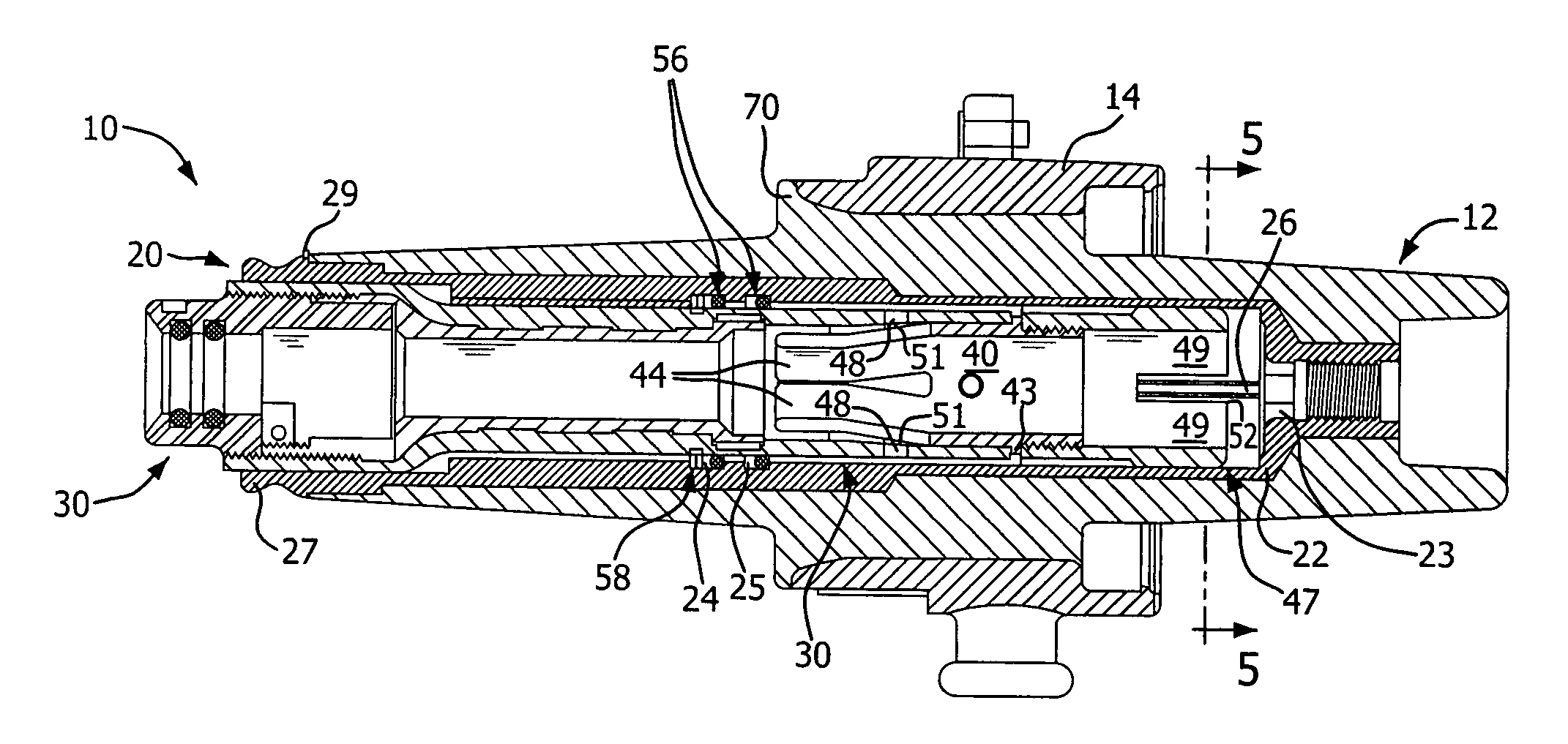
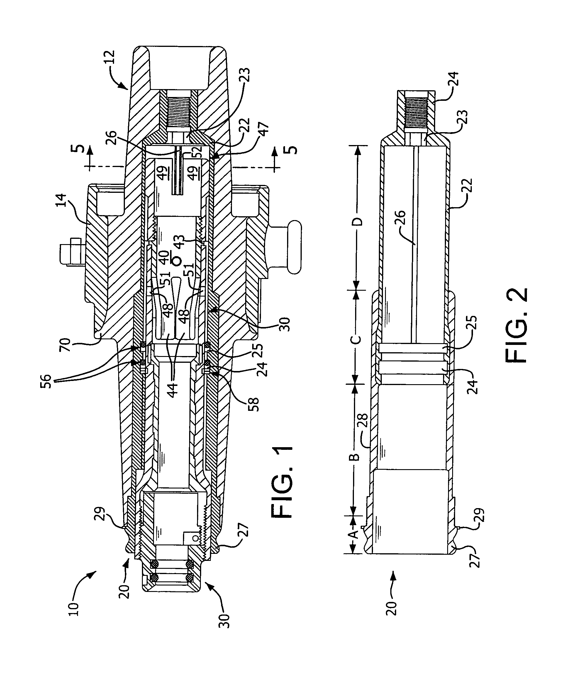
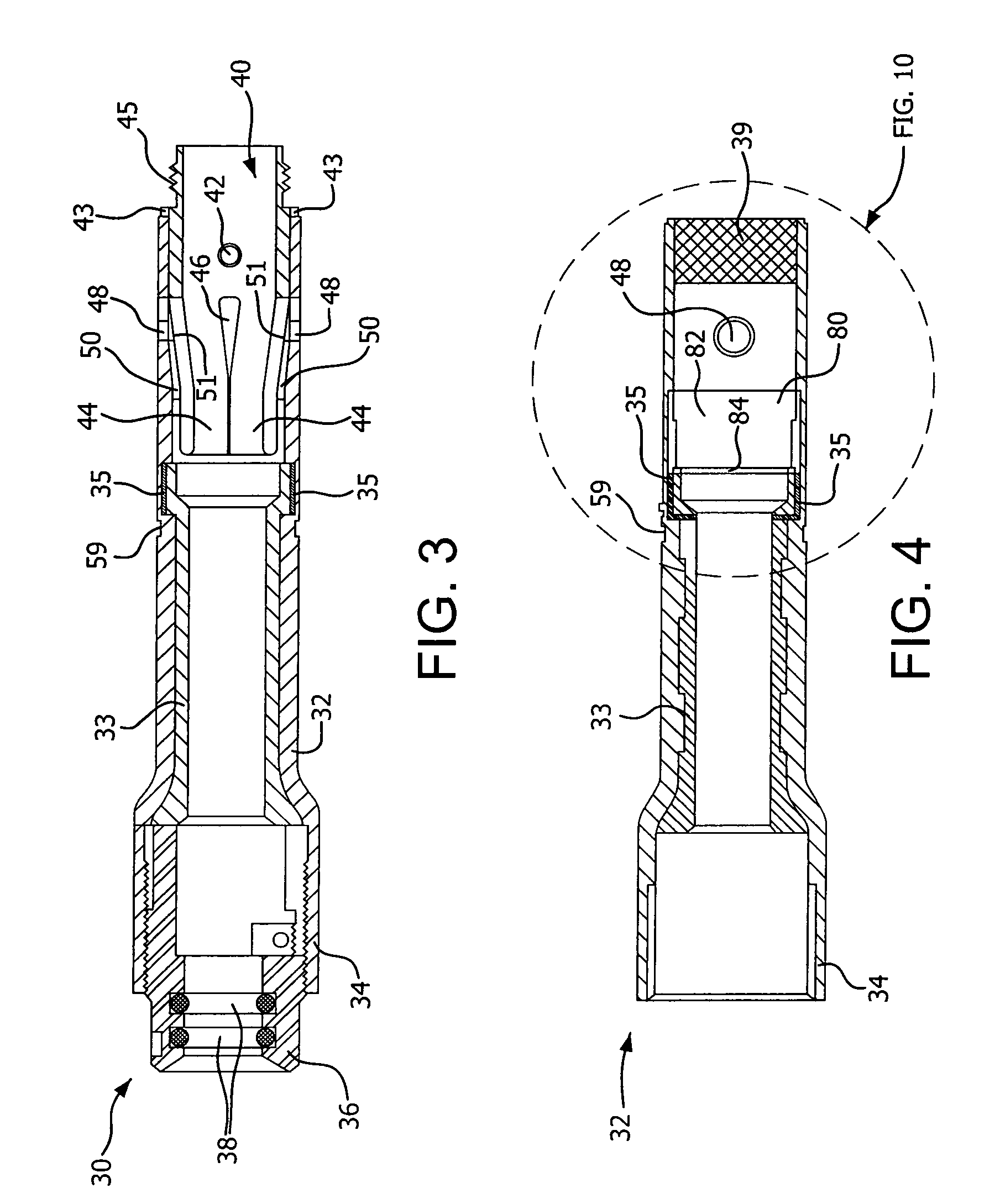
[0024]Referring to FIG. 1, an electrical connector in the form of a bushing insert 10 comprises a molded unitary housing 12 formed of an insulating rubber surrounded in its middle portion by an outer layer 14 made of a conductive rubber, which is connected to ground. Housing 12 is molded around a nose cone assembly 20 (see FIG. 2), which houses a slidable, gas-driven snuffer load break assembly 30 (see FIG. 4). Operation of the snuffer load break assembly is similar to that described in U.S. Pat. No. 7,059,879.

[0025]Referring to FIG. 2, nose cone assembly 20 comprises a copper container 22 having at one end a hexagonal well leading to an internally threaded nipple 24 for connecti...


PUM


Abstract

A high-voltage electrical connector includes a strategically placed barrier that acts as an arc shield to reduce the ionization of materials during load break switching, reducing or preventing flashover. An electric stress graded interface design also reduces switching flashover and reduces the fault close energy. Mating features on the piston-contact element and inside the surrounding container accurately guide the piston-contact element as it travels along the container.

Description

CROSS-REFERENCE TO RELATED APPLICATION[0001]This application claims the benefit of provisional application No. 61 / 213,684, filed Jul. 2, 2009, which is incorporated by reference herein in its entirety.FIELD OF THE INVENTION[0002]The present invention generally relates to an electrical connector for a high voltage power distribution system. More specifically, the invention relates to an electrical connector, such as a bushing insert, having a snuffer tube assembly including a piston-contact element that moves between retracted and extended positions.BACKGROUND OF THE INVENTION[0003]Conventional high voltage electrical connectors, such as bushing inserts, connect devices such as transformers to the electrical equipment of a power distribution system. Typically the electrical connector is joined to another electrical device of the power distribution system, such as an elbow cable connector, with female contacts of the electrical connector mating with male contacts of the cable connecto...

Claims


Application Information

Patent Timeline
Patent Type & Authority Patents(United States)
IPC IPC(8): H01R13/53
CPCH01R13/111H01R13/53
Inventor KUMAR, SENTHIL A.BOGGS, TODD C.
Owner HUBBELL INC
Learn More