Floor panel

a technology for floor panels and panels, applied in the field of floor panels, can solve the problems of high degree of impact noise dampening of materials, and achieve the effects of simple and fast installation, and improved impact noise dampening

Active Publication Date: 2011-12-06
I4F LICENSING NV +2
View PDF22 Cites 96 Cited by
  • Summary
  • Abstract
  • Description
  • Claims
  • Application Information

AI Technical Summary

Benefits of technology

[0008]It is therefore an object of the invention, to create a floor panel of the type mentioned above, which

Problems solved by technology

Because of its relatively soft core of plastic, especially of PVC or p

Method used


Image

  • Floor panel
  • Floor panel
  • Floor panel

Examples


Embodiment Construction

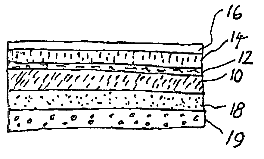
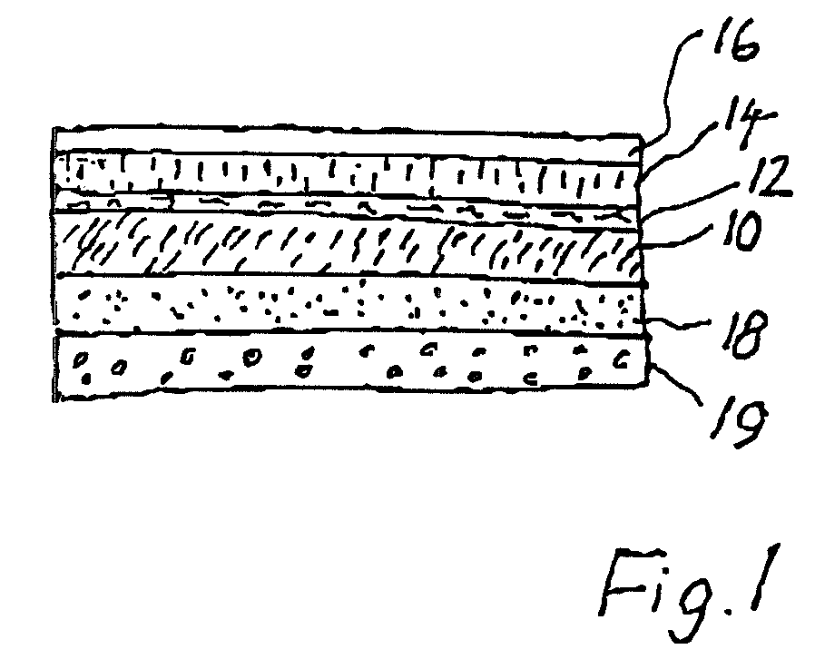
[0027]To begin with, reference is made to FIG. 1. The center of the inventive floor panel is a core 10 of a relatively highly filled, but still elastic plastic, especially PVC or polyurethane. On the core, there is a décor layer 12, such as a printed PVC film, which may be a décor of any type, for example a wood décor or also a stone décor and also any décor imaginable. The décor layer 12 is covered by a use surface or a finishing layer 14, which has a high abrasion resistance. Finally, there is a UV curable layer 16 on the surface. Curing by UV light has the particular advantage that the manufacturing process is accelerated. On the back of the panel, there is a counteracting layer, which prevents curvature of the panel during expansion and shrinkage.

[0028]At the underside of the panel, a damping layer 19 may be provided, which additionally contributes to damping the sound of steps and / or of room noise. The layer 18 of FIG. 1 may, in addition, carry out the function of a back pull a...


PUM

PropertyMeasurementUnit
Lengthaaaaaaaaaa
Densityaaaaaaaaaa
Thicknessaaaaaaaaaa

Abstract

The invention relates to a floor panel in the form of a multilayer, rectangular laminate with a soft core (10) of plastic, a décor film (12) on the upper side of the core (10), a transparent finishing layer (14) and a transparent lacquer layer (16) applied on the finishing layer (16), as well as a back-pull layer (18) on the back of the core (10), with a lockable tongue and groove connection at least at two mutually opposite edges of the panel (20, 22).

Description

BACKGROUND OF THE INVENTION[0001]The invention relates to a floor panel in the form of a rectangular plastic plate according to the introductory portion of claim 1.[0002]A floor panel in the form of a rectangular plastic plate with tongue and groove profiling at least at two mutually opposite edges is known from the British patent 1,430,423. In comparison to a conventional tongue and groove connection, the tongue and groove profiling used has the special feature that the tongue and groove can be locked to one another so that adjacent plates can be prevented from drifting apart in the plane in which they are laid. In the present context, a connection of this type is to be referred to as a lockable tongue and groove connection.[0003]Recently, tongue and groove connections have been employed widely in the course of the success of the so-called laminated floor panels. In practice, because of the possibility of locking adjacent panels together in a springy fashion, click connections are ...

Claims


Application Information

Patent Timeline
IPC IPC(8): B32B27/08
CPCB32B3/02B32B3/06E04F15/10Y10T428/24777Y10T428/195Y10T428/162Y10T428/192F16B5/0004
Inventor WINDMOLLER, ULRICH
Owner I4F LICENSING NV
Why Eureka
Try Eureka