Method and system for providing a magnetic writer using a BARC

a magnetic writer and barc technology, applied in the field of providing a magnetic writer using a barc, can solve the problems of adversely affecting the performance and manufacturability of the conventional pmr head, adversely affecting the photolithography used in patterning the photoresist layer, and achieving the effect of low reflectivity

Active Publication Date: 2011-12-06
WESTERN DIGITAL TECH INC
View PDF10 Cites 153 Cited by
  • Summary
  • Abstract
  • Description
  • Claims
  • Application Information

AI Technical Summary

Benefits of technology

[0008]A method and system for providing a magnetic writer are described. The method and system comprise providing a bottom antireflective coating (BARC) on a portion of the magnetic writer. The BARC has a low reflect

Problems solved by technology

As a result, placing the resist layer 70 directly on the conventional seed layer 66 would adversely affect photolithography used in patterning the photoresist layer 70 in step 18.
Although the conventional BARC layer 68 improves the photolithography, use of the conventional BARC layer 68 results in footin

Method used


Image

  • Method and system for providing a magnetic writer using a BARC
  • Method and system for providing a magnetic writer using a BARC
  • Method and system for providing a magnetic writer using a BARC

Examples


Embodiment Construction

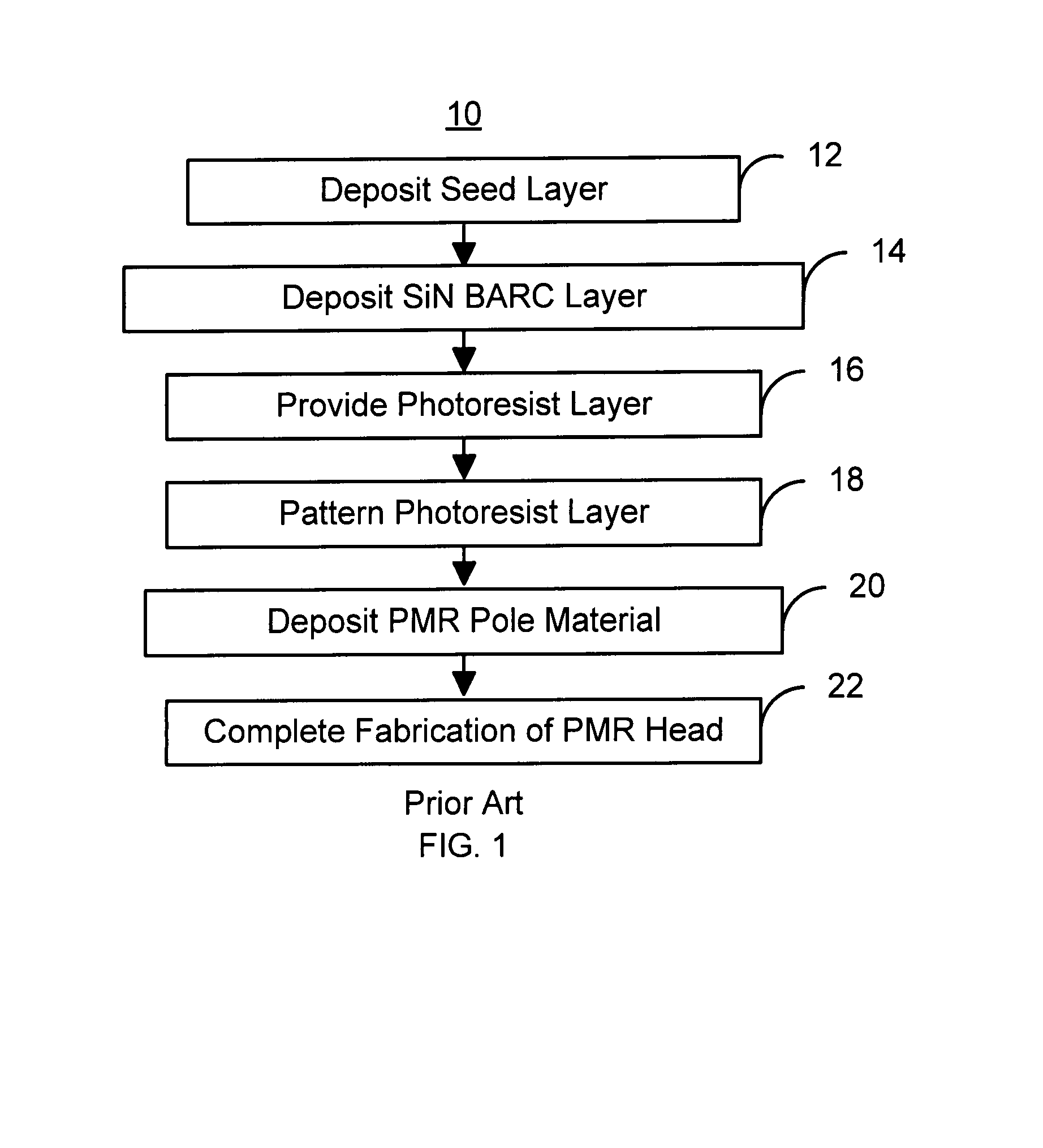
[0014]FIG. 5 is a flow chart depicting an exemplary embodiment of a method 100 for fabricating a structure in a write transducer, such as a PMR head. The method 100 is described in the context of and preferably used for providing a PMR pole of a PMR head. However, in another embodiment, the method 100 may be used in providing another structure that may be in another type of head. For example, the method 100 may be used in providing a conductive line.

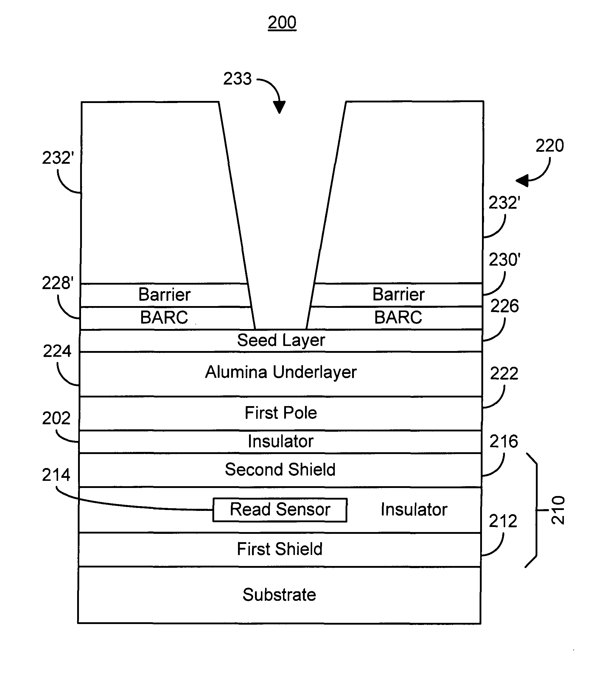
[0015]A BARC is provided on a portion of the magnetic writer, via step 102. In a preferred embodiment, the BARC is provided on a seed layer, such as Ru, for a PMR pole. The BARC has a low reflectivity and is preferably SiN. However, in another embodiment, other and / or additional materials may be used. Further, in an alternate embodiment, the BARC may be a multilayer.

[0016]A barrier layer is provided on at least a portion of the BARC, via step 104. In a preferred embodiment, the thickness of the barrier layer is sufficient to isolate at l...


PUM


Abstract

A method and system for providing a magnetic writer are described. The method and system include providing a bottom antireflective coating (BARC) on a portion of the magnetic writer. The BARC has a low reflectivity. The method and system also include providing a barrier layer on at least a portion of the BAR and providing a mask on at least a portion of the barrier layer. The barrier layer isolates the BARC from the mask.

Description

BACKGROUND[0001]FIG. 1 depicts a conventional method 10 for fabricating a conventional perpendicular magnetic recording (PMR) pole of a conventional PMR transducer. FIGS. 2-4 depict the conventional PMR head 50 during fabrication using the conventional method 10 as viewed from the air-bearing surface (ABS). For clarity, the conventional PMR head 50 is not to scale. Referring to FIGS. 1-4, the method 10 commences after formation of an alumina underlayer. A conventional seed layer, such as Ru, is deposited, via step 12. A conventional bottom antireflective coating (BARC) layer of SiN is typically, deposited, via step 14. The conventional BARC layer may be used to reduce or eliminate reflections from the underlying substrate[0002]A photoresist layer is provided on the conventional BARC is provided on the conventional BARC layer, via step 16. FIG. 2 depicts the conventional PMR head 50 after step 16 is provided. The conventional PMR head 50 is typically a merged head including a convent...

Claims


Application Information

Patent Timeline
IPC IPC(8): G11B5/147
CPCG11B5/1278G11B5/3133G11B5/3163
Inventor WANG, YIZHONGZHANG, HONGSUN, HAIYUAN, HONGPINGYU, WINNIE
Owner WESTERN DIGITAL TECH INC
Why Eureka
Try Eureka