Sensing device having a large diameter D-shaped optical waveguide

a technology of optical waveguides and sensors, applied in the field of optical sensors, can solve the problems of fiber with d-shapes, high loss of fibers, and difficult manufacturing, and achieve the effects of improving packaging options, facilitating use and manufacturing, and inherent mechanical rigidity

Inactive Publication Date: 2011-12-06
WEATHERFORD TECH HLDG LLC
View PDF15 Cites 2 Cited by
  • Summary
  • Abstract
  • Description
  • Claims
  • Application Information

AI Technical Summary

Benefits of technology

[0008]The invention generally relates to an optical sensor formed from an optical waveguide that permits access to the evanescent field and is easy to use and manufacture. The optical sensor includes an outer cladding having at least one inner core disposed therein that propagates light. A portion of the optical sensor has a generally D-shaped cross-section and a transverse outer waveguide dimension that is greater than about 0.3 mm. The large outer diameter D-shape of the sensor has inherent mechanical rigidity to improve packaging options, reduce bend losses, and resist damage from handling. Further, advantages for grating writing into the sensor in the D-shaped section due to the flat surface include lower power, better optical absorption by the core, and easier alignment. Axial or compressive strain across the D-shaped cross section may be determined by measuring the change in polarization or birefringence of the light output from the sensor. In one embodiment, a layer responsive to a parameter is disposed on a flat portion of the D-shaped portion of the sensor. The refractive index of the layer changes and / or the layer applies a strain on the sensor in response to the parameter. Changes in the refractive index of the layer alters the light output from the sensor, which is measured over time and correlated to the parameter.

Problems solved by technology

When a portion of a cladding of an optical fiber is removed to create a D-shaped fiber portion, the fiber becomes fragile due to the small diameter of the cladding, e.g., about 125 microns.
The fiber with the D-shape is highly lossy, difficult to manufacture and difficult to use because the fiber is delicate and fragile.

Method used


Image

  • Sensing device having a large diameter D-shaped optical waveguide
  • Sensing device having a large diameter D-shaped optical waveguide
  • Sensing device having a large diameter D-shaped optical waveguide

Examples


Embodiment Construction

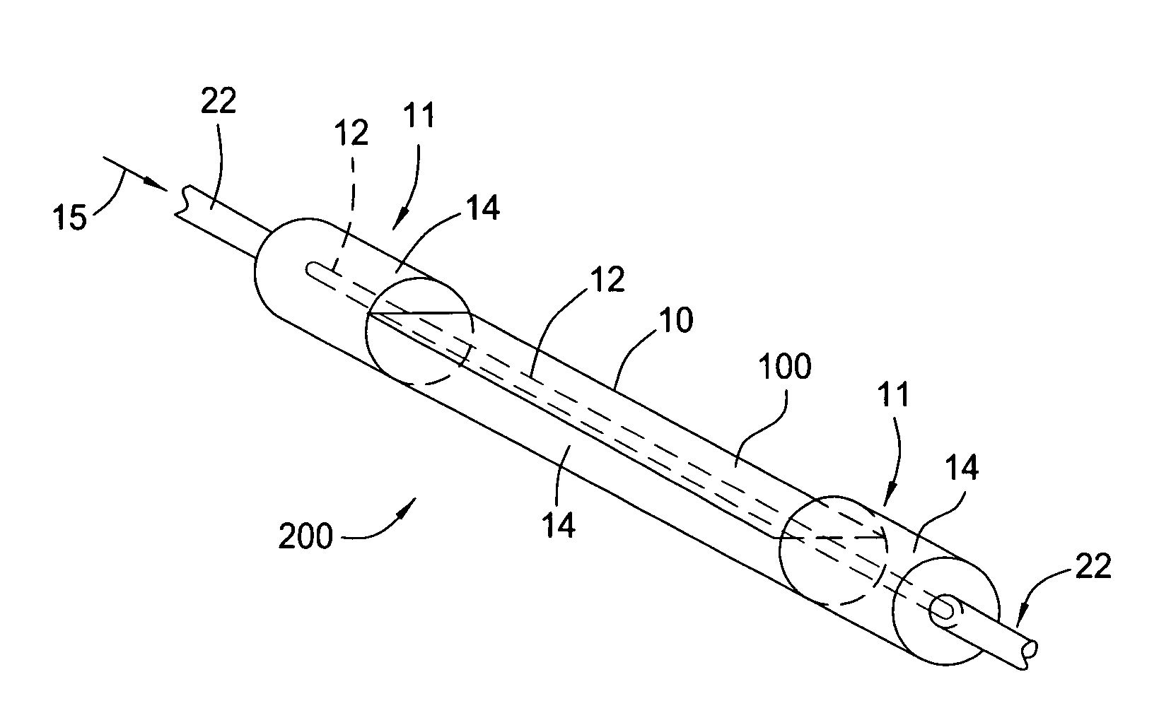
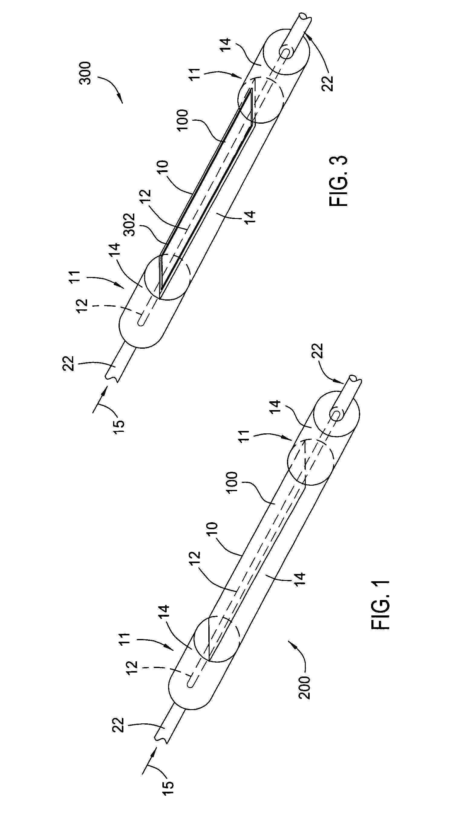
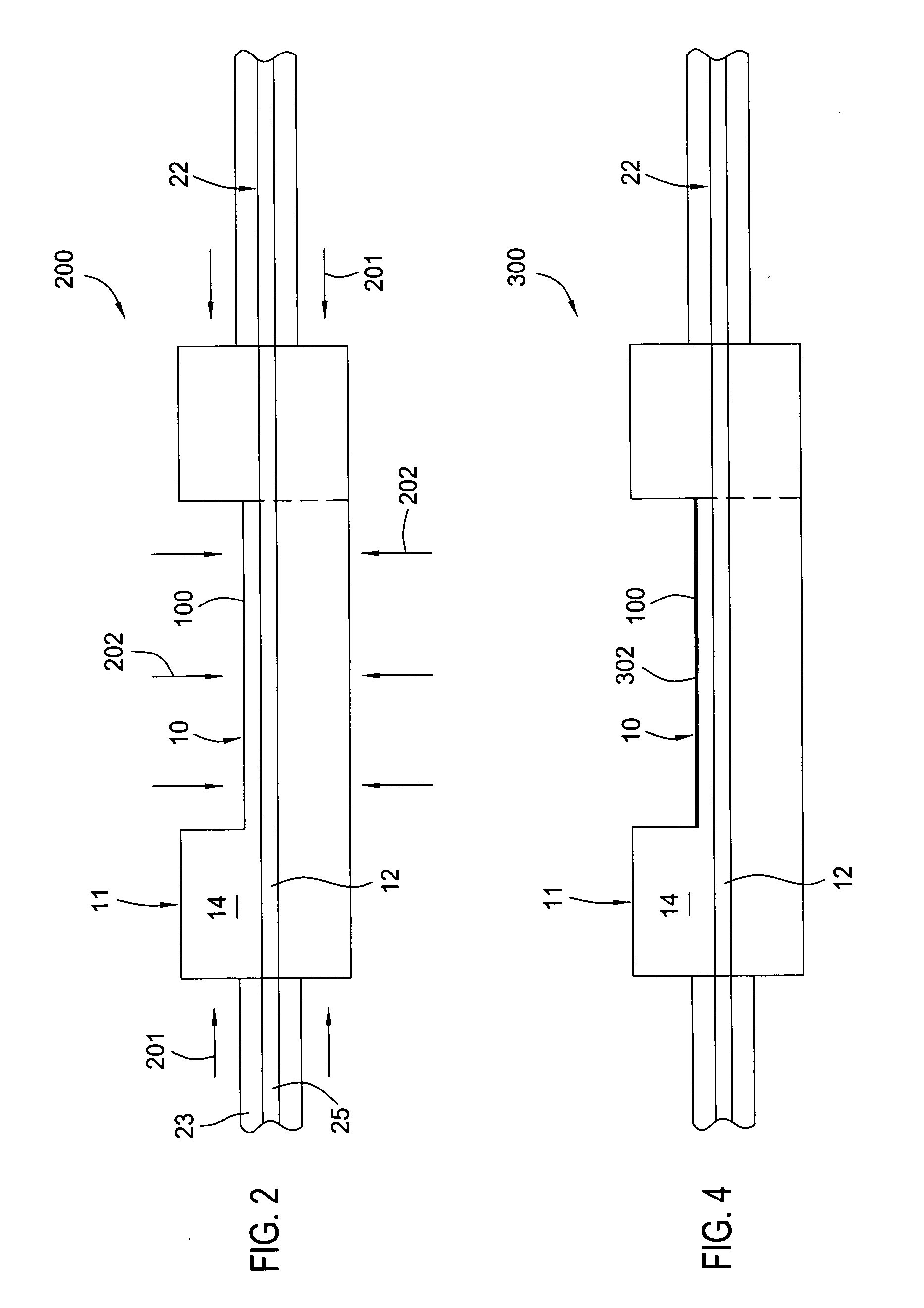
[0016]FIGS. 1 and 2 illustrate a large diameter D-shaped optical sensor 200 that is a waveguide with a generally D-shaped portion 10 and at least one core 12 surrounded by a cladding 14. Additionally, the shape of the waveguide forming the sensor 200 may include one or more circular portions 11. The sensor 200 comprises silica glass (SiO2) based material having the appropriate dopants to allow light 15 to propagate in either direction along the core 12 and / or within the sensor 200. Other materials for the sensor 200 may be used such as any glass material, e.g., silica, phosphate glass, other glasses, or solely plastic. Further, the sensor 200 may be a birefringent, polarization maintaining, polarizing, multi-core, or multi-cladding optical waveguide. The cladding 14 has an outer dimension of at least about 0.3 millimeters and the core 12 has an outer dimension such that it propagates the desired number of spatial modes. Thus, the outer dimension of the cladding 14 of the sensor 200 ...


PUM

PropertyMeasurementUnit
diameteraaaaaaaaaa
temperatureaaaaaaaaaa
birefringenceaaaaaaaaaa

Abstract

An optical sensor formed from an optical waveguide having at least one core surrounded by a cladding and a large diameter generally D-shaped portion is disclosed. Axial or compressive strain across the D-shaped cross section may be determined by measuring the change in polarization or birefringence of the light output from the sensor. A layer responsive to a parameter may be disposed on a flat portion of the D-shaped portion of the sensor. The refractive index of the layer changes and/or the layer applies a strain on the sensor in response to the parameter. Changes in the refractive index of the layer alters the light output from the sensor, which is measured over time and correlated to the parameter.

Description

CROSS-REFERENCE TO RELATED APPLICATIONS[0001]This application claims benefit of U.S. Provisional Patent Application Ser. No. 60 / 439,716, filed Jan. 13, 2003, which is herein incorporated by reference. This application is a continuation-in-part of U.S. patent application Ser. No. 10 / 098,891, filed Mar. 18, 2002 now U.S. Pat. No. 6,996,316 , which is herein incorporated by reference.BACKGROUND OF THE INVENTION[0002]1. Field of the Invention[0003]The invention relates to optical sensors. More particularly, the invention relates to optical sensors formed from an optical waveguide with a large outer transverse diameter and a substantially D-shaped portion.[0004]2. Description of the Related Art[0005]Various industries and applications utilize optical sensors to measure parameters such as temperatures, pressures, and chemicals in a particular environment. In particular, optical sensors are finding increased applications in civil, industrial, and military fields where enhanced sensitivity,...

Claims


Application Information

Patent Timeline
Patent Type & Authority Patents(United States)
IPC IPC(8): G02B6/00G02B6/02G01B11/16G01D5/353G01K11/32G01L1/24G02B6/28G02B6/34G02B6/42H01S3/067H01S3/094
CPCG01B11/18G01D5/35377G01L1/242G02B6/02052G02B6/02057G02B6/274G02B6/2817G02B6/2821H01S3/0675G01D5/3538G01K11/32G02B6/2826G02B6/29334G02B6/4214H01S3/06708H01S3/094003H01S3/094007H01S3/094019Y10T29/49815Y10T29/49817G01D5/353G02B6/02G02B6/03611G02B6/03627G02B6/03644G02B6/29377
Inventor KERSEY, ALAN D.SANDERS, PAUL E.PUTNAM, MARTIN A.DOWD, EDWARD MICHAEL
Owner WEATHERFORD TECH HLDG LLC
Why Eureka
Try Eureka