Plasma processing apparatus, radio frequency generator and correction method therefor

a processing apparatus and radio frequency generator technology, applied in waveguide type devices, fluid pressure measurement, instruments, etc., can solve the problems of long calibration process, troublesome process, power loss of radio frequency power, etc., to prevent noise effect of radio frequency generator calibration, reduce time to calibrate radio frequency generator, and reduce process time

Active Publication Date: 2011-12-06
TOKYO ELECTRON LTD
View PDF29 Cites 9 Cited by
  • Summary
  • Abstract
  • Description
  • Claims
  • Application Information

AI Technical Summary

Benefits of technology

[0031]In view of the above, the present invention provides a plasma processing apparatus capable of significantly reducing time to calibrate output power of a radio frequency generator, for example, when calibrating the radio frequency generator order to compensate for a power loss caused by a transmission line, and also preventing noise effect in calibrating the radio frequency generator.

Problems solved by technology

However, if several plasma processing apparatuses are operating, a power loss of the radio frequency power incurred by a transmission line extending from the radio frequency generator to the electrodes in the processing chamber varies depending on each apparatus even though the output power of the radio frequency generator coupled to each processing apparatus is the same.
Further, since an overshoot occurs if the power-setting voltage level is changed too much, the operator has to gradually change the power-setting voltage level several times while monitoring the power meter 40.
Accordingly, the calibration process takes a long time.
This process is troublesome in that the calibration process takes more time.
Further, since the power-setting voltage signal 60 transmitted to the radio frequency generator 10 from the generator control unit 50 is an analog signal, it is easily affected by noise.
Particular when the set power level of radio frequency power becomes smaller, the power-setting voltage level for adjusting the output power becomes accordingly smaller, which aggravates the noise problem.
That is, if the target radio frequency power is low, the power-setting voltage signal 60 is significantly affected by the overlapped noise and therefore it may be difficult to accurately control the output power level of the radio frequency generator 10.
Furthermore, attenuation characteristics of the radio frequency power during the transmission thereof from the radio frequency generator to the electrode in the processing chamber are not uniform.
Due to this, in case of using only the above-described techniques for adjusting the output power during plasma processing, it is difficult to maintain the radio frequency power applied to the electrode of the processing chamber at a specific value.
Otherwise, it is very difficult to adjust the radio frequency power actually supplied to the electrode in the processing chamber with high accuracy.

Method used


Image

  • Plasma processing apparatus, radio frequency generator and correction method therefor
  • Plasma processing apparatus, radio frequency generator and correction method therefor
  • Plasma processing apparatus, radio frequency generator and correction method therefor

Examples


first embodiment

[0068](Configuration of Plasma Processing Apparatus in First Embodiment)

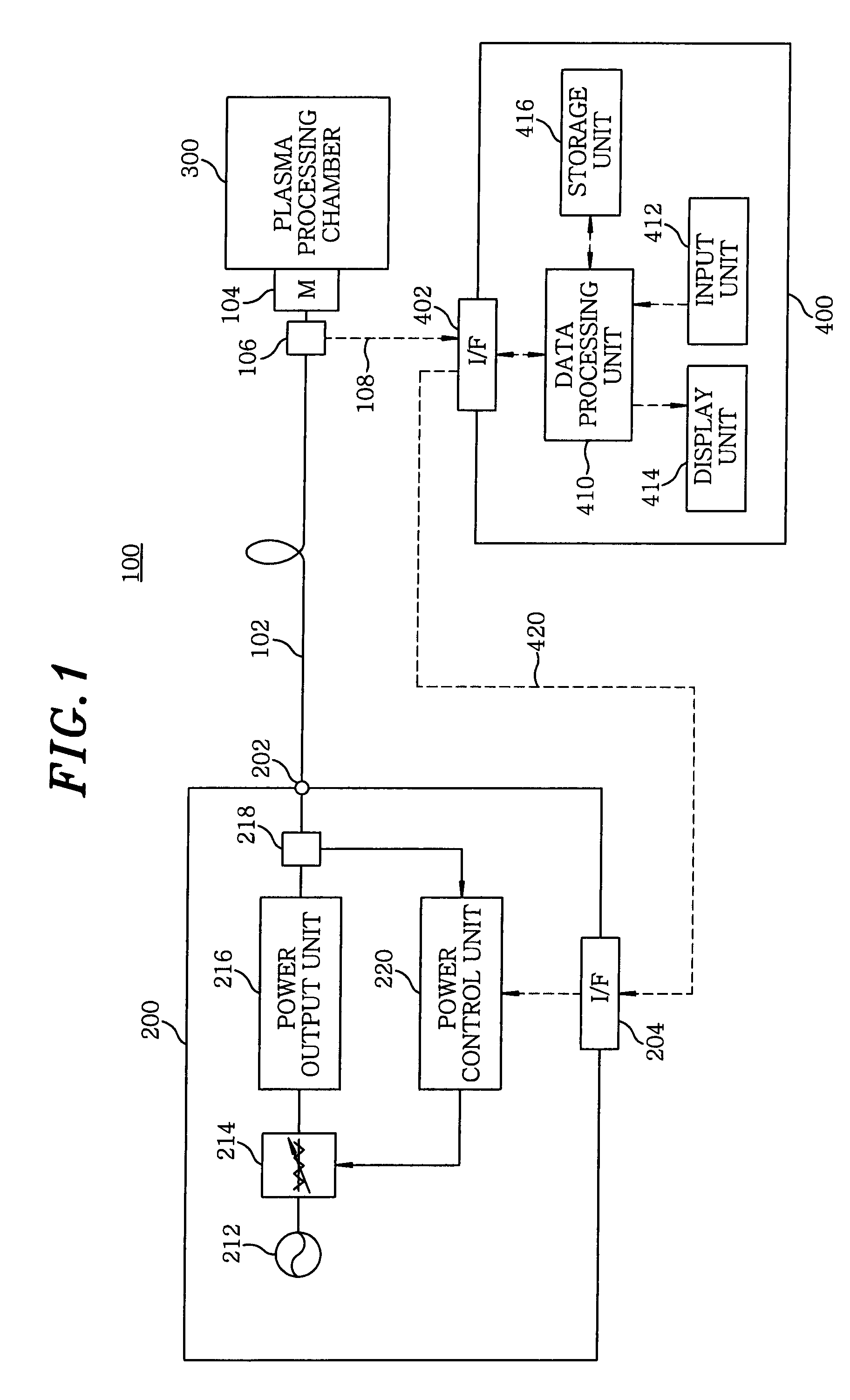
[0069]First, the configuration of a plasma processing apparatus 100 in accordance with the first embodiment of the present invention will be described with reference to the drawings. FIG. 1 is a block diagram showing the configuration of the plasma processing apparatus 100 in accordance with the first embodiment of the present invention.

[0070]As shown therein, the plasma processing apparatus 100 includes a radio frequency generator 200; a coaxial cable 102 whose one end is coupled to a power output terminal 202 of the radio frequency generator 200; a matching unit 104 connected to the other end of the coaxial cable 102; and a plasma processing chamber (hereinafter, simply referred to as a “chamber”) 300 connected to the matching unit 104. The plasma processing apparatus 100 also includes a power detection unit 106 interposed between the other end of the coaxial cable 102 and the matching unit 104; and a generato...

second embodiment

[0139](Configuration of Plasma Processing Apparatus in Second Embodiment)

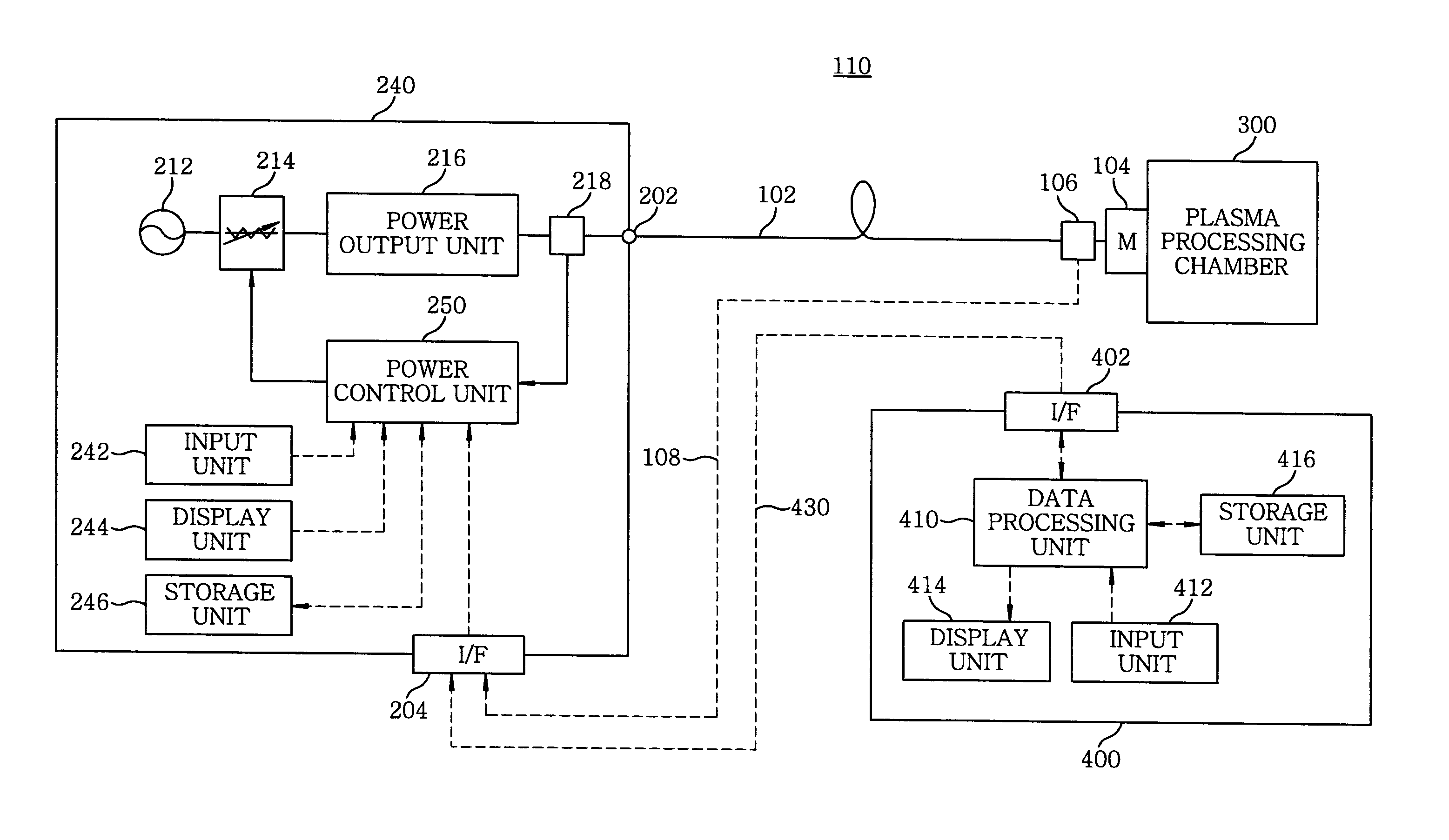
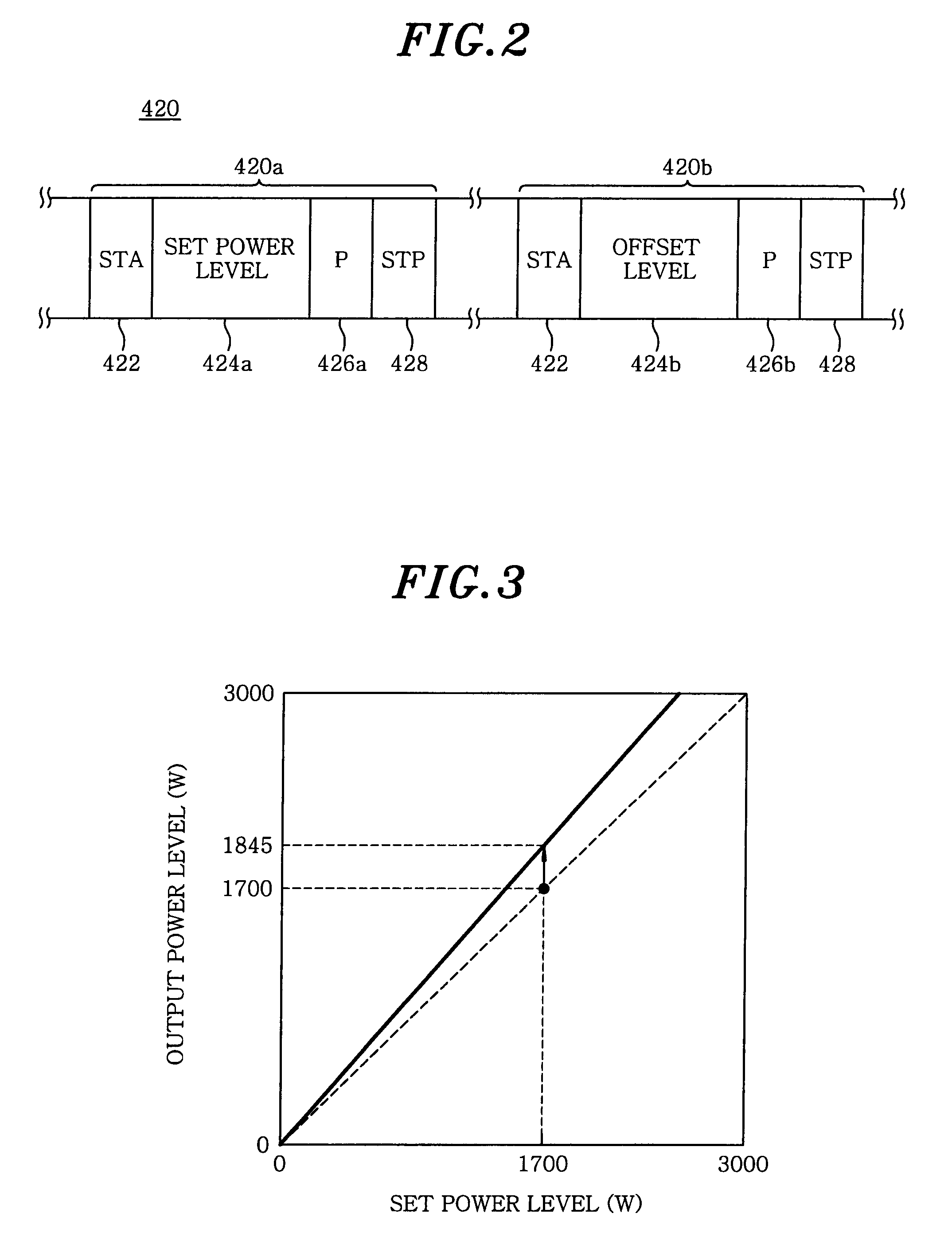
[0140]In the plasma processing apparatus 100 of the first embodiment, the radio frequency generator 200 receives the power supply control signal 420 from the generator control unit 400 and adjusts the target output power level based on the set power level 424a and the offset level 424b contained in the power supply control signal 420. On the contrary, a plasma processing apparatus 110 of the second embodiment is configured in such a way that a radio frequency generator 240 receives a power detection signal 108 directly from a power detection unit 106 and a power supply control signal 430 from a generator control unit 400. FIG. 5 is a block diagram showing a configuration of the plasma processing apparatus 110 of the second embodiment of the present invention.

[0141]As shown in FIG. 5, the plasma processing apparatus 110 includes the radio frequency generator 240, a coaxial cable 102 whose one end is coupled to a...


PUM

PropertyMeasurementUnit
impedanceaaaaaaaaaa
voltageaaaaaaaaaa
poweraaaaaaaaaa

Abstract

A plasma processing apparatus includes a radio frequency generator capable of adjusting a target output power level based on the set power level and the offset level to output radio frequency power; a chamber in which a plasma process is performed; and a power detection unit for measuring radio frequency power level fed to the matching unit. The plasma processing apparatus further includes a generator control unit for controlling the radio frequency power such that the radio frequency power level fed to the matching unit reaches the set power level by calculating the offset level based on the difference between the set power level and the power level measured by the power detection unit and transmitting the set power level and the offset level in digital form to the data input terminal of the radio frequency generator.

Description

FIELD OF THE INVENTION[0001]The present invention relates to a plasma processing apparatus, a method for calibrating a radio frequency generator and a radio frequency generator.BACKGROUND OF THE INVENTION[0002]In a manufacturing process of semiconductor devices, a plasma processing apparatus for performing an etching process or a film forming process on a semiconductor wafer (hereinafter, referred to as a “wafer”) by high density plasma generated at a relatively low pressure atmosphere conventionally has been used. For example, in case of a parallel plate type plasma processing apparatus, a pair of parallel plate type electrodes, i.e., an upper electrode and a lower electrode, are disposed in a processing chamber, a processing gas is introduced into the processing chamber and at the same time radio frequency power is supplied to either or both electrodes from a radio frequency generator to generate a radio frequency electric field between the electrodes. The radio frequency electric...

Claims


Application Information

Patent Timeline
Patent Type & Authority Patents(United States)
IPC IPC(8): H01L21/306
CPCH01J37/32082H01J37/32174H01J37/32183H01J37/32935
Inventor SATO, KENJI
Owner TOKYO ELECTRON LTD
Why Eureka
Try Eureka