
Fuel injection and mixing systems having piezoelectric elements and methods of using the same

a piezoelectric element and mixing system technology, applied in the direction of hydrogen/synthetic gas production, combustion air/fuel air treatment, hydrogen/synthetic gas production, etc., can solve the problems of high manufacturing cost, fuel cell industry facing several critical challenges, and preventing them from being accepted for a wide variety of applications, so as to improve the mixing and uniformity of feed streams, minimize pressure loss, and optimize the effect of injector performan

Active Publication Date: 2011-12-13
DELAVAN
View PDF43 Cites 15 Cited by
  • Summary
  • Abstract
  • Description
  • Claims
  • Application Information

AI Technical Summary

Benefits of technology

"The present invention provides a fuel injection and mixing system for a fuel processor that can operate with liquid fuels, hot air, and steam. The system includes a piezoelectric fuel atomizer that can vaporize liquid fuels and achieve complete mixing at low fuel flow rates. The system also includes a mixing chamber that delivers a well-mixed flow of fuel and gases with uniform velocity and temperature distribution over the entire reactor face. The system can be adapted and configured to interact with fuel droplets and prevent carbon formation. The technical effects of the invention include improved fuel atomization, mixing, and combustion in fuel cells."

Problems solved by technology

Although various types of fuel cells have been installed for commercial use, high manufacturing costs have largely prohibited them from being accepted for a wide variety of applications.
In addition to high manufacturing cost, the fuel cell industry is faced with several critical challenges that must be resolved before fuel cell systems can be fully commercialized for wide spread power generation applications.
Current state-of-the-art fuel processors are limited to using gaseous fuels, such as natural gas, hydrogen and liquefied petroleum gas (LPG).
Currently, liquid fuel processing technology is not yet viable for commercial applications in SOFC systems.
One technical barrier for liquid fuel processing is reactor durability.
The performance of the reforming catalysts quickly deteriorates as a result of carbon deposition, sulfur poisoning and loss of precious metals due to sintering or evaporation at high temperatures.
Poor feed stream preparation such as inadequate atomization, wall impingement, and non-uniform mixing can easily lead to local conditions that favor carbon deposition and formation of hot spots in the reactor.
In most mobile APU applications, there are very limited supply pressures available for liquid atomization and feed stream mixing, making it especially challenging for the design and development of fuel injection and mixing systems.

Method used


Image

  • Fuel injection and mixing systems having piezoelectric elements and methods of using the same
  • Fuel injection and mixing systems having piezoelectric elements and methods of using the same
  • Fuel injection and mixing systems having piezoelectric elements and methods of using the same

Examples


Embodiment Construction

[0040]Reference will now be made in detail to the present preferred embodiments of the invention, examples of which are illustrated in the accompanying drawings. The method and corresponding steps of the invention will be described in conjunction with the detailed description of the system.

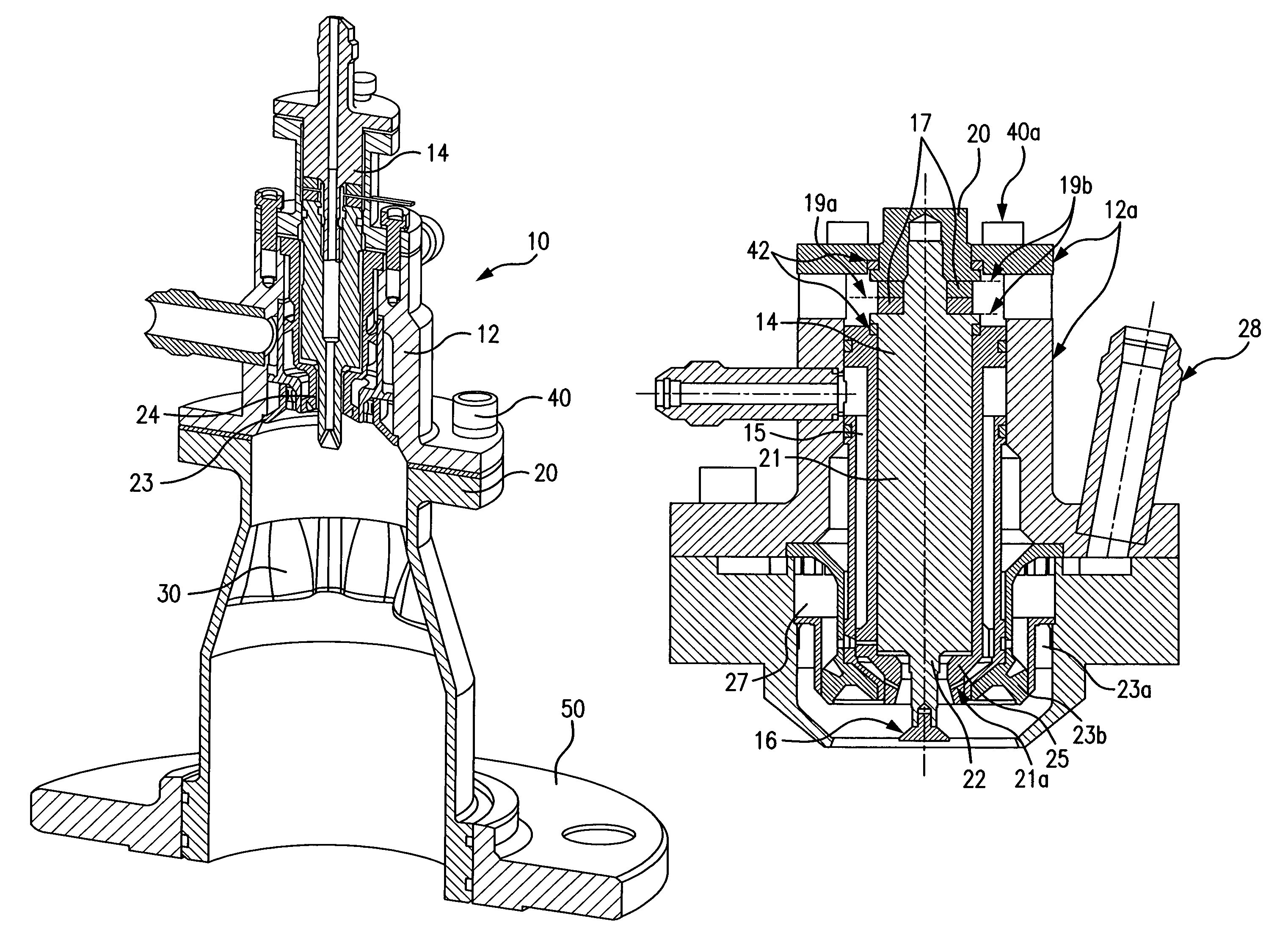
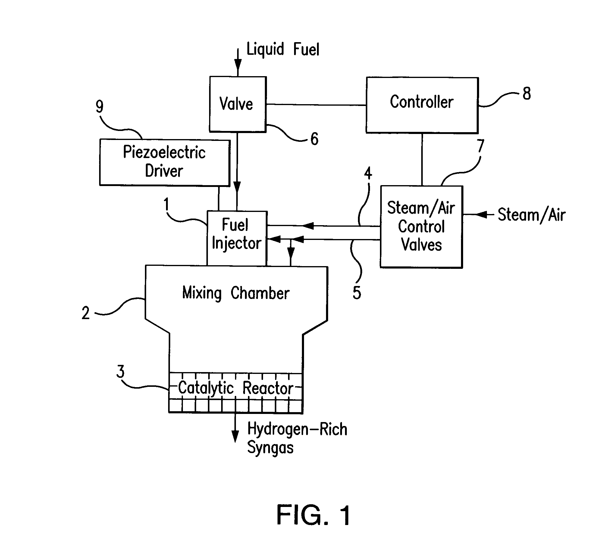
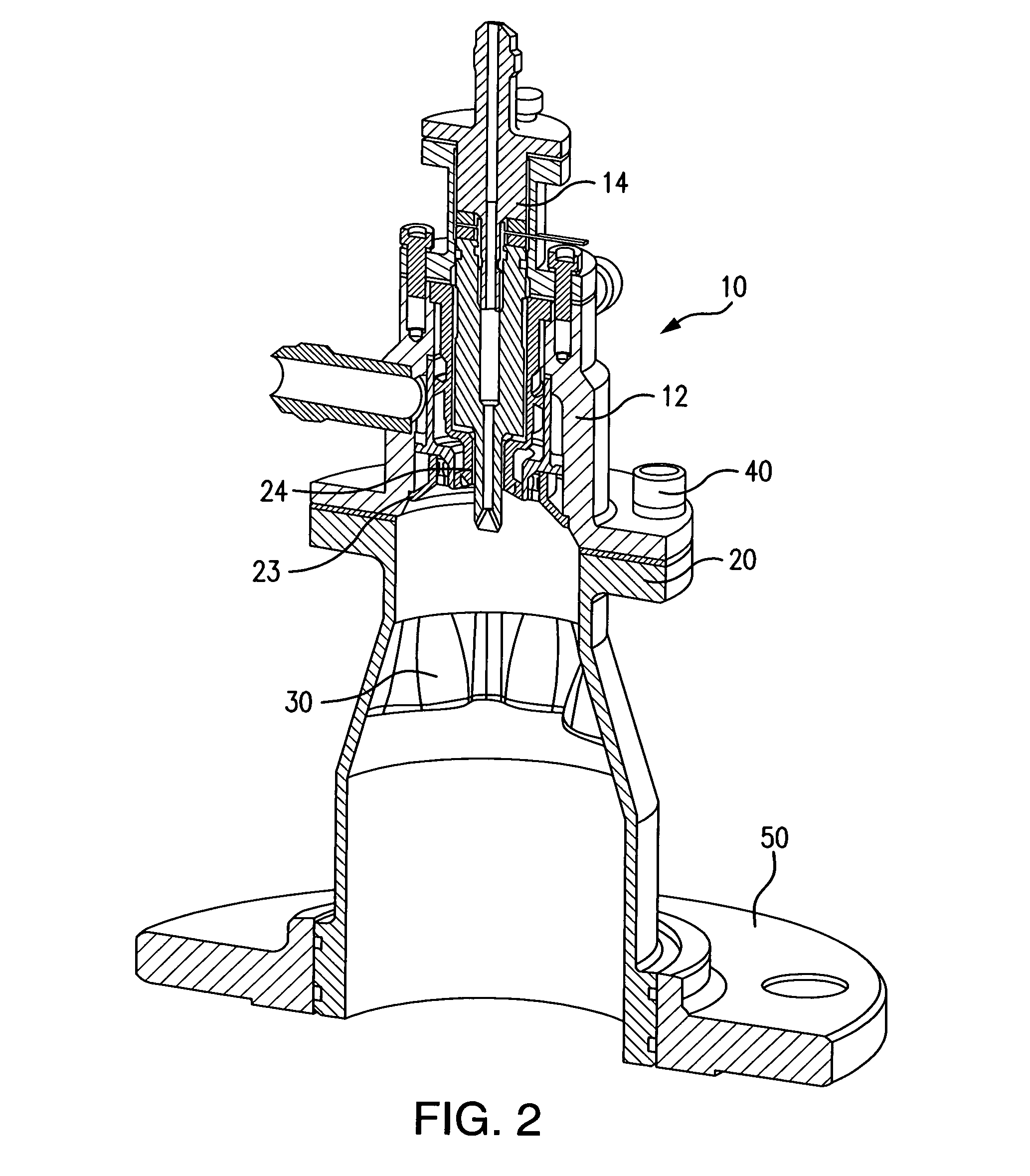
[0041]For purpose of explanation and illustration, and not limitation, a partial view of an exemplary embodiment of a fuel injection and mixing system in accordance with the invention is shown in FIG. 2 and is designated generally by reference character 10. Other embodiments of a fuel injection and mixing system in accordance with the invention, or aspects thereof, are provided in FIGS. 1 and 3-11, as will be described.

[0042]In accordance with the invention, a fuel injection and mixing system is provided that is suitable for use with various types of fuel reformers. Preferably, the system includes a piezoelectric injector for delivering atomized fuel, gas swirler(s), such as a steam and / or an air ...


PUM

PropertyMeasurementUnit
mass flow rateaaaaaaaaaa
swirl angleaaaaaaaaaa
resonant frequencyaaaaaaaaaa

Abstract

A fuel injection and mixing system is provided that is suitable for use with various types of fuel reformers. Preferably, the system includes a piezoelectric injector for delivering atomized fuel, a gas swirler, such as a steam swirler and / or an air swirler, a mixing chamber and a flow mixing device. The system utilizes ultrasonic vibrations to achieve fuel atomization. The fuel injection and mixing system can be used with a variety of fuel reformers and fuel cells, such as SOFC fuel cells.

Description

CROSS-REFERENCE TO RELATED APPLICATIONS[0001]This application claims the benefit of priority of U.S. Provisional Application Ser. No. 60 / 791,602 filed Apr. 12, 2006. This application is incorporated by reference herein in its entirety.GOVERNMENT SUPPORT[0002]The Government has rights in this invention, pursuant to Contract No. DE-FC26-04NT42229 awarded by the U.S. Department of Energy.FIELD OF THE INVENTION[0003]The present invention relates to fuel injection and mixing systems. Particularly, the present invention is directed to an integrated fuel injection and mixing system for fuel reformers or fuel processors to generate hydrogen-rich gas, such as for fuel cell applications.BACKGROUND OF THE INVENTION[0004]Fuel cells are an emerging technology that can significantly improve energy efficiency and energy security. Fuel cell technology can provide environmentally friendly electrical energy, producing far fewer harmful pollutants and lower levels of noise than conventional power gene...

Claims


Application Information

Patent Timeline
Patent Type & Authority Patents(United States)
IPC IPC(8): B05B1/08B05B3/04F02M7/22
CPCC01B3/38F02M25/12F02M27/08F02M31/18H01M8/04201H01M8/0618Y02E60/525C01B2203/0244C01B2203/0261C01B2203/066C01B2203/1276H01M2008/1293Y02T10/121Y02T10/126Y02E60/50C01B2203/0233Y02T10/12
Inventor MAO, CHIEN-PEISHORT, JOHNKLEMM, JIMABBOTT, ROYCEOVERMAN, NICKPACK, SPENCERWINEBRENNER, AUDRA
Owner DELAVAN
Learn More