Marine vessel propulsion device and marine vessel including the same

a technology for propulsion devices and marine vessels, applied in the direction of vessel construction, automatic control, instruments, etc., can solve the problems of large loads being applied to parts of the shift drive unit and the shift mechanism unit, and the misfiring is started from a subsequent spark plug

Active Publication Date: 2011-12-13
YAMAHA MOTOR CO LTD
View PDF7 Cites 6 Cited by
  • Summary
  • Abstract
  • Description
  • Claims
  • Application Information

AI Technical Summary

Benefits of technology

With the marine vessel propulsion device having such an arrangement, when the shift operational unit is operated to change from the first shift position to the second shift position (when a shift-out operation is performed), misfire control is started to temporarily lower the engine speed. Further, the switching from the transmitting state to the cut-off state is started after the first delay time period has elapsed after the misfire control is started. Thus, even in a case where a lag occurs between the point in time when the shift-out operation is performed and the point in time when the engine speed actually starts to decrease, the shift-out can be executed smoothly. That is, the shift drive unit can be driven to reliably start the switching from the transmitting state to the cut-off state after the engine speed actually starts to decrease. The shift-out can thus be executed reliably in a state in which loads applied to the shift drive unit and the shift mechanism unit are small. Also, a consumption power of the shift drive unit, such as a shift drive motor, can be reduced because the load applied to the shift drive unit can be lightened.
Preferably, the control unit may be arranged to control the shift drive unit such that the shift mechanism unit starts the switching from the transmitting state to the cut-off state in an initial period in which the engine speed starts to decrease. With this configuration, the shift-out (switching from the transmitting state to the cut-off state) can be ended as early as possible after the shift-out operation by the user. Recognition by the user of the lag of execution of the shift-out due to the lag of the start of driving of the shift drive unit can thereby be effectively suppressed and minimized.
In a preferred embodiment of the present invention, an engine speed commanding unit, which is arranged to issue a command to maintain the engine speed at a predetermined rotation speed based on an operation of the user, preferably is provided separately from the shift operational unit. In this case, the control unit may be arranged to control the engine speed based on a state of the engine speed commanding unit. Preferably, the control unit is arranged such that, in a case where the engine speed is controlled based on the state of the engine speed commanding unit, the control unit starts the misfire control after elapse of a second delay time period from the operation of the shift operation unit from the first shift position to the second shift position and controls the shift drive unit such that the shift mechanism unit starts the switching from the transmitting state to the cut-off state after elapse of the first delay time period after the start of the misfire control. The inventor has discovered, in developing the preferred embodiments of the present invention, that a problem may arise when the shift-out operation is performed with a high engine speed being maintained based on the command by the state engine rotation commanding unit. That is, there may be a case where the engine speed has not decreased adequately when the shift switching operation is performed after elapse of just the first delay time period from the shift-out operation. Further delay by the first delay time period is thus carried out preferably after delaying by the second delay time period from the point in time when the shift-out operation is performed. The shift mechanism unit thus starts the switching from the transmitting state to the cut-off state in the state where the engine speed has decreased sufficiently. The shift-out can thereby be executed reliably in the state in which the loads applied to the shift drive unit and the shift mechanism unit are small.

Problems solved by technology

Thus, in actuality, misfiring is started from a subsequent spark plug.
There is thus an issue that large loads are consequently applied to portions of the shift drive unit and the shift mechanism unit.

Method used


Image

  • Marine vessel propulsion device and marine vessel including the same
  • Marine vessel propulsion device and marine vessel including the same
  • Marine vessel propulsion device and marine vessel including the same

Examples


first preferred embodiment

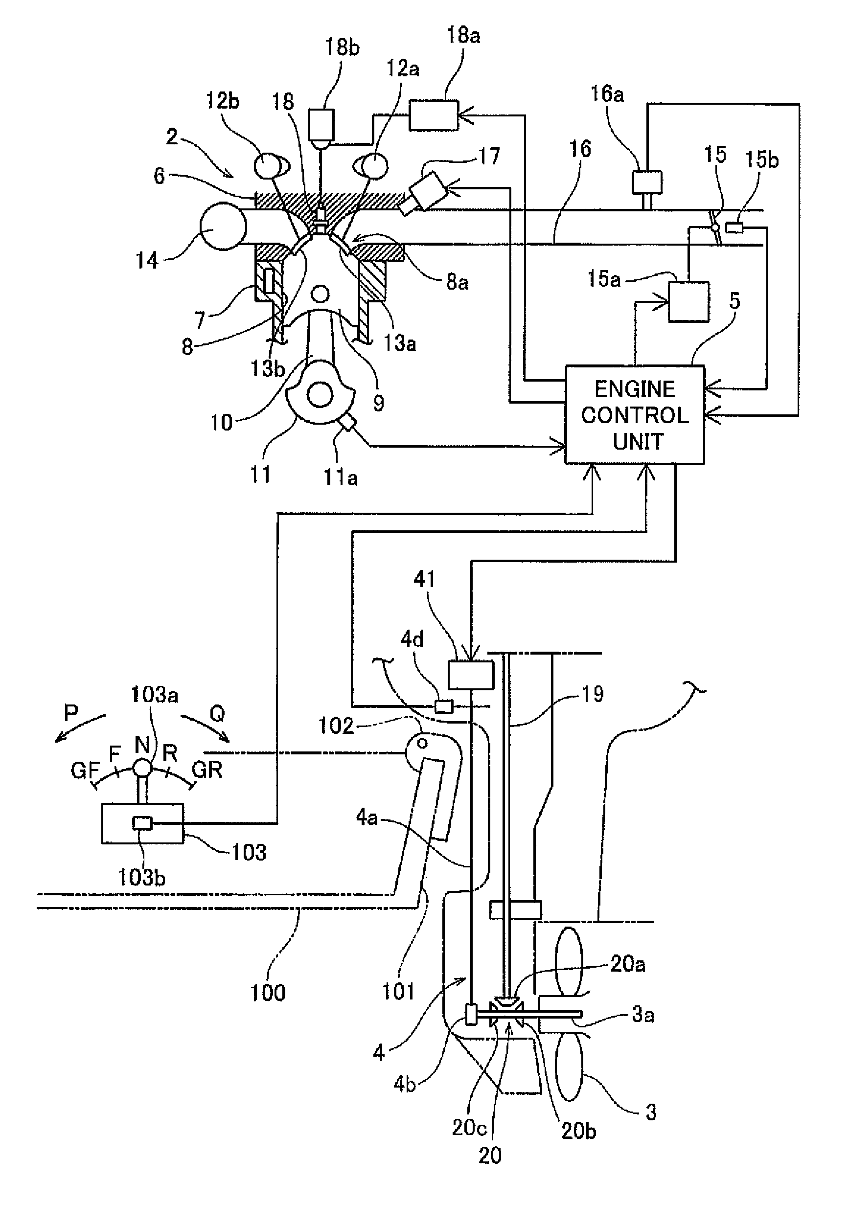
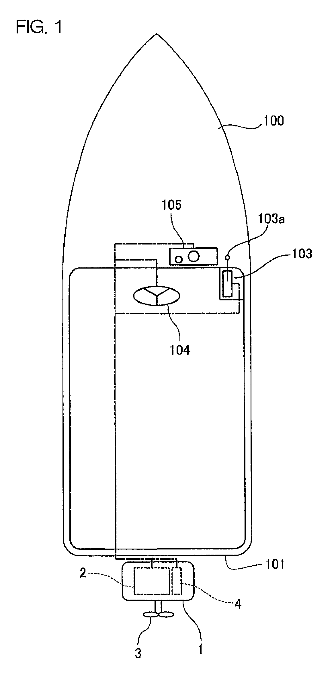
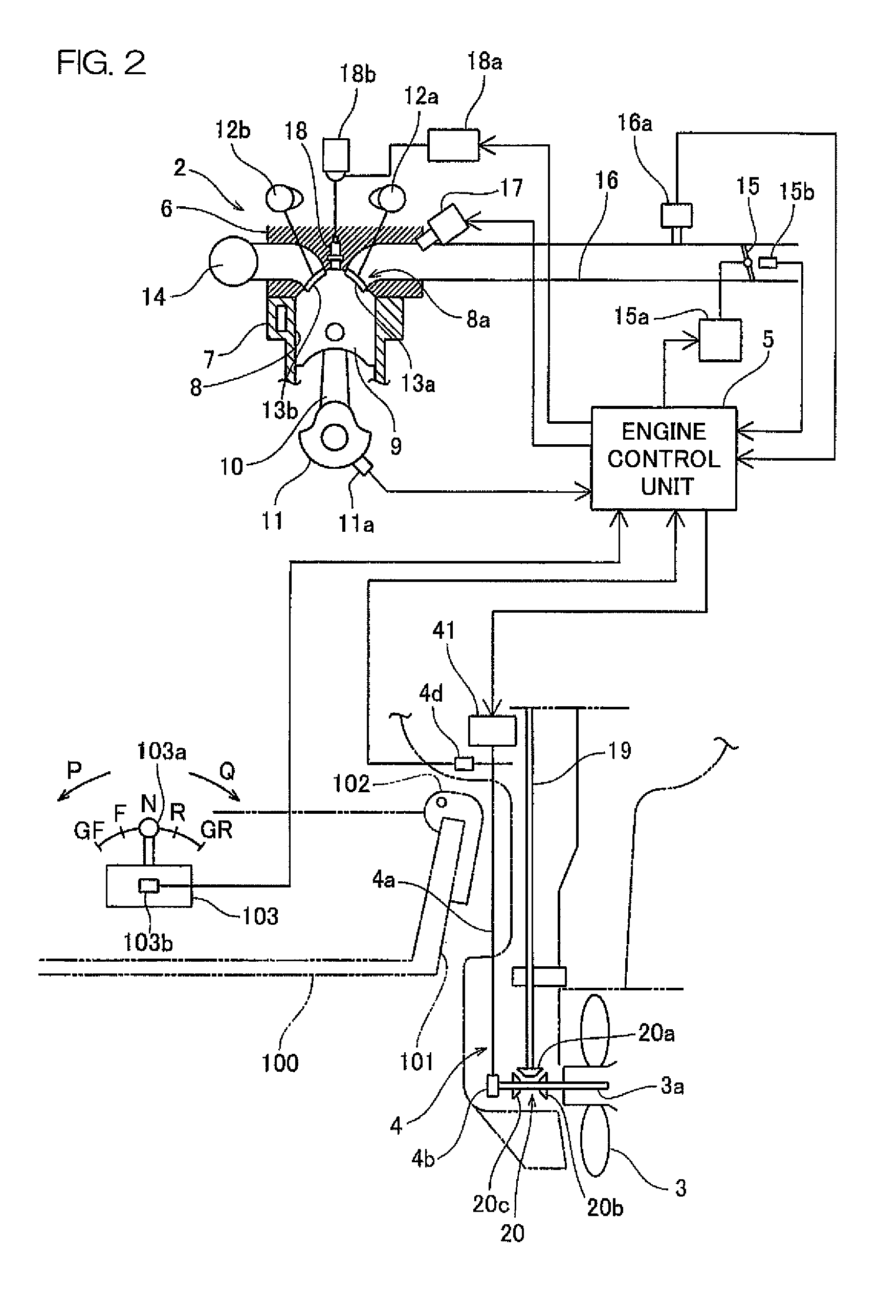
FIG. 1 is a schematic plan view of an overall configuration of a marine vessel that includes an outboard motor according to a first preferred embodiment of the present invention. In the present preferred embodiment, an outboard motor 1, which is one example of a marine vessel propulsion device, is attached to a stern 101 of a hull 100. The outboard motor 1 includes an engine 2, a propeller 3 arranged to be rotated by a driving force of the engine 2, and a forward-reverse switching mechanism unit 4. In addition, the propeller 3 and the forward-reverse switching mechanism unit 4 are, respectively, one example of a “thrust generating unit” and one example of a “shift mechanism unit” according to a preferred embodiment of the present invention.

A remote control apparatus 103, a steering apparatus 104, and a display unit 105 are installed at a central portion of the hull 100. The remote control apparatus 103 is arranged to be operated by a user to command a throttle opening of the engine ...

second preferred embodiment

FIGS. 6 and 7 are, respectively, a flowchart and a timing chart for explaining an operation of controlling the engine and the forward-reverse switching mechanism unit by the ECU of an outboard motor according to a second preferred embodiment of the present invention. The structures of the marine vessel and the outboard motor according to the second preferred embodiment preferably are the same as those of the first preferred embodiment shown in FIGS. 1 to 3. Also, the flowchart of FIG. 6 differs from the flowchart of FIG. 4 in that step S12 is carried out between step S3 and step S4.

In the second preferred embodiment, the lag time period (predicted lag time period) from the point in time when the misfire control is started to the point in time when the misfiring is actually started is computed (predicted). In the second preferred embodiment, after starting the misfire control in step S3, the ECU 5 computes the lag time amount based on the engine speed at the point in time when the mi...

third preferred embodiment

FIG. 8 is a timing chart for explaining an operation of controlling the engine and the forward-reverse switching mechanism unit by the ECU of an outboard motor according to a third preferred embodiment of the present invention. The above described FIG. 6 shall be referred to again in regard to the control operation. Also, the structures of the marine vessel and the outboard motor according to the third preferred embodiment are preferably the same as those of the first preferred embodiment shown in FIGS. 1 to 3.

Unlike in the second preferred embodiment, the ECU 5 determines the ignition timing by using a timer in the third preferred embodiment. Specifically, in the third preferred embodiment, after starting the misfire control in step S3 of FIG. 6, the ECU 5 predicts the maximum lag time amount in step S12 of FIG. 6. That is, the ECU 5 uses the engine speed at the point in time when the misfire control is started, the number of cylinders (for example, four cylinders in the third pref...


PUM


Abstract

A marine vessel propulsion device includes an engine arranged to generate a driving force by combustion of a fuel by an ignition unit, a thrust generating unit arranged to be driven by the driving force of the engine to generate thrust underwater, a shift mechanism unit arranged to switch between a transmitting state of transmitting the driving force of the engine to the thrust generating unit and a cut-off state of cutting off the driving force of the engine from the thrust generating unit, a shift drive unit arranged to drive the shift mechanism unit, and a control unit arranged to electrically control the shift drive unit based on a position of a shift operational unit that is arranged to be operated by a user to perform a shifting operation to a first shift position corresponding to the transmitting state, and a second shift position corresponding to the cut-off state. When changing from the first shift position to the second shift position, the control unit temporarily lowers an engine speed by starting misfire control of the ignition unit. After the start of the misfire control, the control unit controls the shift drive unit such that the shift mechanism unit starts the switching from the transmitting state to the cut-off state after a delay time period corresponding to a time from the start of misfire control to a point in time when the ignition unit actually starts to misfire.

Description

BACKGROUND OF THE INVENTION1. Field of the InventionThe present invention relates to a marine vessel propulsion device that includes a shift mechanism unit. The shift mechanism unit is configured to switch between a transmitting state, in which a driving force of an engine is transmitted to a thrust generating unit, and a cut-off state, in which the driving force of the engine is cut off from the thrust generating unit. The present invention also relates to a marine vessel that includes such a marine vessel propulsion device.2. Description of the Related ArtAn outboard motor is one example of a marine vessel propulsion device. An outboard motor according to one prior art is disclosed in Japanese Unexamined Patent Application publication No. 2005-113904. This outboard motor includes a shift mechanism unit. The shift mechanism unit is capable of switching between a transmitting state, in which a driving force of an engine is transmitted to a propeller (thrust generating unit), and a c...

Claims


Application Information

Patent Timeline
Patent Type & Authority Patents(United States)
IPC IPC(8): B60W10/04B63H21/21B63H20/14F02D29/00F02P5/15F02P9/00F16D48/02
CPCB63H21/265B63H20/001B63H20/20
Inventor ITO, MAKOTO
Owner YAMAHA MOTOR CO LTD
Why Eureka
Try Eureka