Remote plasma cleaning source having reduced reactivity with a substrate processing chamber

Inactive Publication Date: 2011-12-13
APPLIED MATERIALS INC
View PDF23 Cites 33 Cited by
  • Summary
  • Abstract
  • Description
  • Claims
  • Application Information

AI Technical Summary

Benefits of technology

[0009]The present invention provides a method and apparatus for cleaning a chamber in a substrate processing system that is less destructive to the chamber walls and the components contained therein, while increasing the number of wafers that may be processed between wet cleans. The present invention does so by mixing a diluent gas with a flow of reactive radicals produced

Problems solved by technology

One problem that arises during such CVD processes is that unwanted deposition occurs in the processing chamber and leads to potentially high maintenance costs.
With CVD of a desired film on a wafer, undesired film deposition can occur on any hot surface including the heater or process kit parts of the apparatus, because the reactive gases can diffuse everywhere, even between cracks and around corners, in the processing chamber.
Over time, failure to clean the residue from the CVD apparatus often results in degraded, unreliable processes and defective wafers.
Depending on which and how many parts need replacing and the frequency of the replacement, the cost of maintaining the substrate processing system can become very high.
However, with some metal CVD processes, etching gases useful for etching unwanted metal are often corrosive and attack the materials which make up the chamber, heater, and process kit parts of the processing chamber.
Moreover, use of in situ plasma cleaning al

Method used


Image

  • Remote plasma cleaning source having reduced reactivity with a substrate processing chamber
  • Remote plasma cleaning source having reduced reactivity with a substrate processing chamber
  • Remote plasma cleaning source having reduced reactivity with a substrate processing chamber

Examples


Embodiment Construction

I. Exemplary CVD System

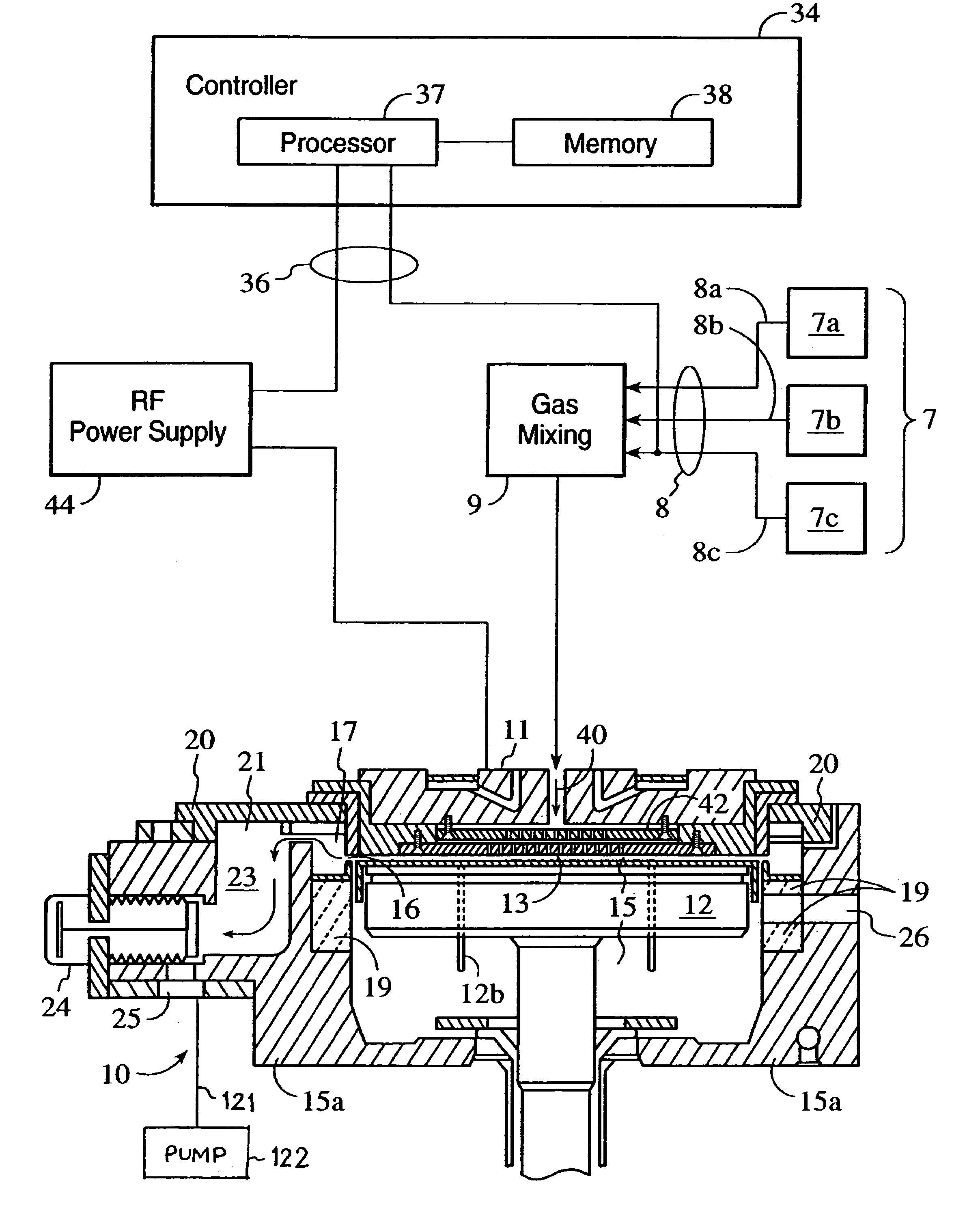
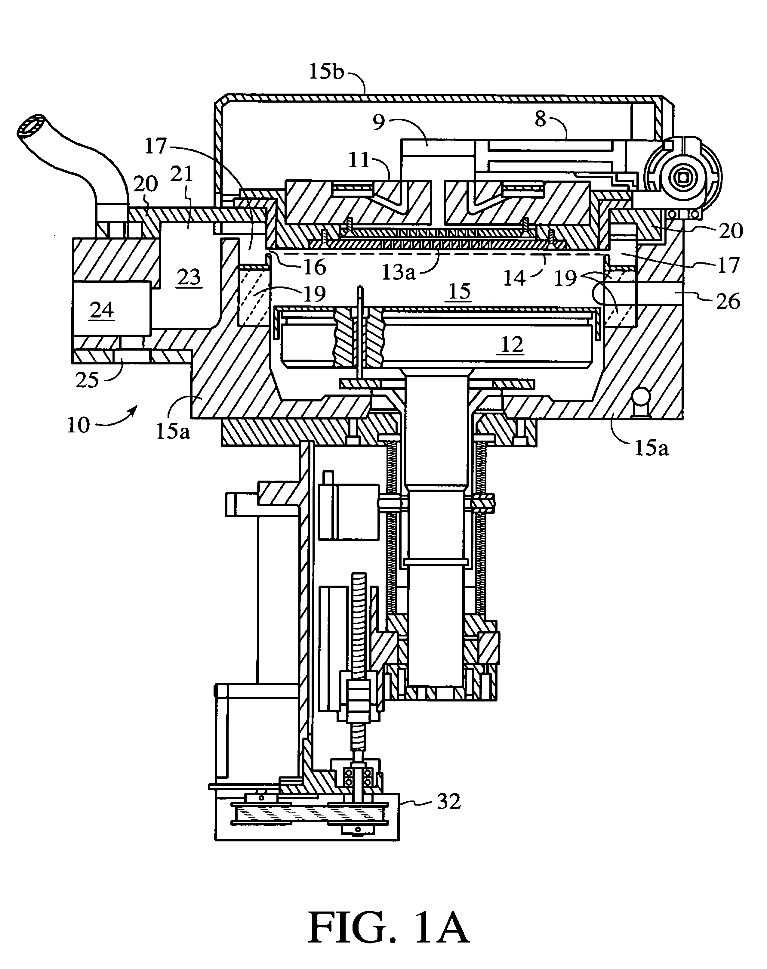
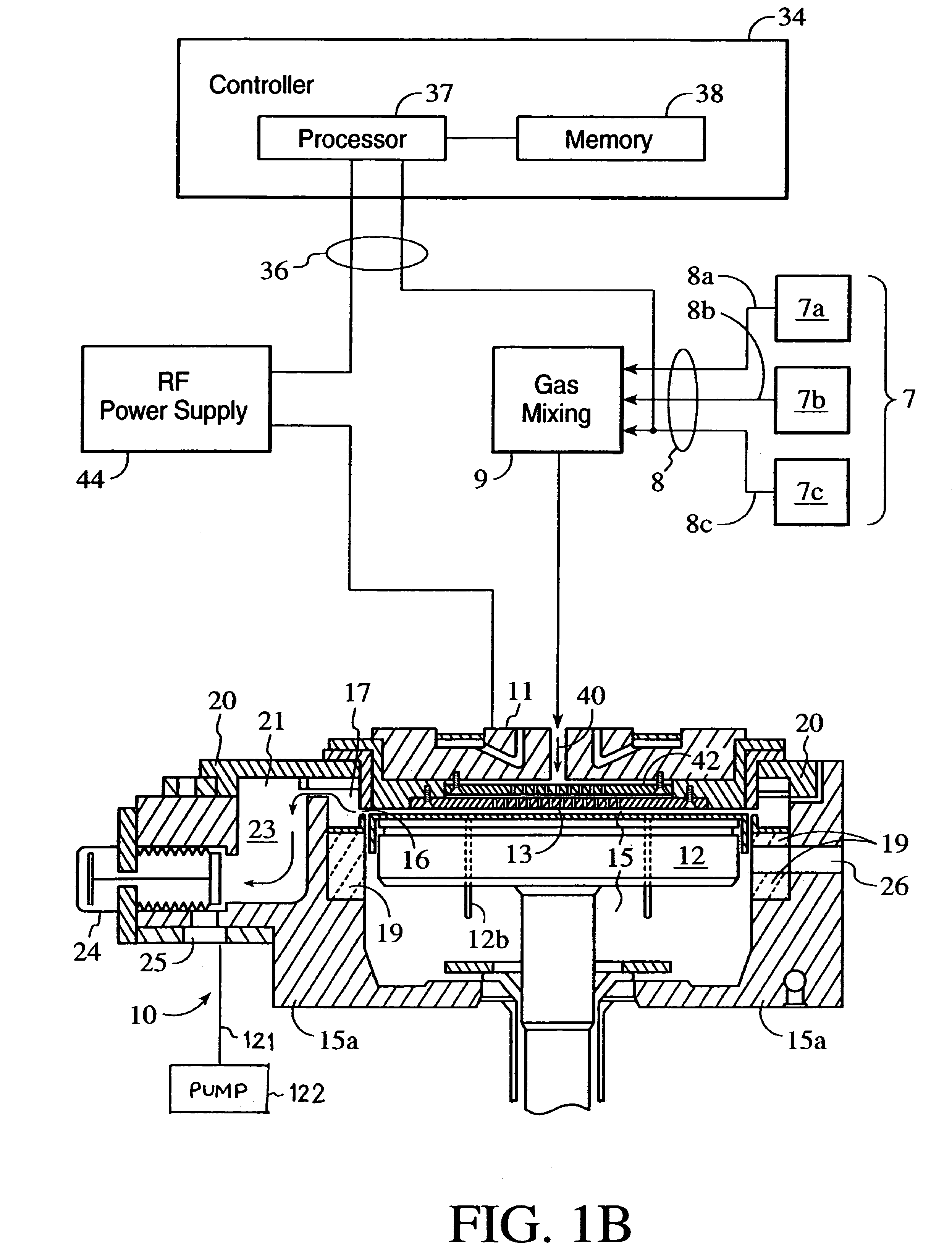
[0028]Specific embodiments of the present invention may be used with or retrofitted onto a variety of chemical vapor deposition (CVD) or other types of substrate processing apparatus. One suitable substrate processing apparatus with which the present invention can be used or retrofitted is shown in FIGS. 1A and 1B, which are vertical, cross-sectional views of a CVD system 10, having a vacuum or processing chamber 15 that includes a chamber wall 15a and chamber lid assembly 15b. Chamber wall 15a and chamber lid assembly 15b are shown in exploded, perspective views in FIGS. 1C and 1D.

[0029]Reactor 10 contains a gas distribution manifold 11 for dispersing process gases to a substrate (not shown) that rests on a resistively-heated pedestal 12 centered within the process chamber. During processing, the substrate (e.g. a semiconductor wafer) is positioned on a flat (or slightly convex) surface 12a of pedestal 12. Preferably having a surface of ceramic such as alumin...


PUM

PropertyMeasurementUnit
Pressureaaaaaaaaaa
Ratioaaaaaaaaaa
Reactivityaaaaaaaaaa

Abstract

A method and apparatus for cleaning a chamber in a substrate processing system having less reactivity with the chamber walls and the components contained therein. The method includes mixing a diluent gas with a flow of radicals produced by a plasma remotely disposed with respect to the chamber, at a point located between a plasma applicator and the chamber. The apparatus includes a fluid manifold having multiple inlets and an outlet with the outlet being coupled to an intake port of the chamber. One of the inlets are in fluid communication with the plasma applicator, with the remaining inlets being in fluid communication with a supply of the diluent gas. In this fashion, the diluent gas flow and the flow of reactive radicals mix when traveling between the inlets and the outlet to form a gas-radical mixture egressing from the outlet and traversing through the intake port.

Description

CROSS REFERENCE TO RELATED APPLICATIONS[0001]This application is related to commonly assigned patent applications entitled “APPARATUS AND METHODS FOR UPGRADED SUBSTRATE PROCESSING SYSTEM WITH MICROWAVE PLASMA SOURCE”, filed on Mar. 5, 1997 as application Ser. No. 08 / 811,627, and having Tsutomu Tanaka, Mukul Kelkar, Kevin Fairbairn, Hari Ponnekanti and David Cheung listed as inventors; “APPARATUS FOR IMPROVED REMOTE MICROWAVE PLASMA SOURCE FOR USE WITH SUBSTRATE PROCESSING SYSTEMS”, filed on Apr. 23, 1997 as application Ser. No. 08 / 839,111, and having Chien-Teh Kao, Kenneth Tsai, Quyen Pham, Ronald L. Rose, Calvin R. Augason, and Joseph Yudovsky listed as inventors (referred to herein as “Kao”); and “METHOD FOR IMPROVED CLEANING OF SUBSTRATE PROCESSING SYSTEMS” filed concurrently herewith as application Ser. No. 08 / 893,922, and having Chien-Tien Kao, Karl Littau, Anand Vasudev and Dong W. Koo listed as inventors; the disclosures of which are hereby incorporated by reference.BACKGROUN...

Claims


Application Information

Patent Timeline
IPC IPC(8): C25F1/00C25F3/30C25F5/00B44C1/22C03C15/00C03C25/68C23F3/00H01L21/205C23C16/44C23C16/452H01J37/32H01L21/304H01L21/31
CPCC23C16/4405C23C16/452H01J37/32862H01L21/304
Inventor LITTAU, KARL A.CHEN, CHILIANG L.VASUDEV, ANAND
Owner APPLIED MATERIALS INC
Why Eureka
Try Eureka