Display backlight with improved light coupling and mixing

a technology of backlight and light coupling, which is applied in the direction of coupling device connection, lighting and heating apparatus, instruments, etc., can solve the problems of light entering the light guide from the edges, assembly fragility, environmental hazardous materials, etc., and achieve the effect of improving color mixing and efficiently mixing

Active Publication Date: 2011-12-20
LIGHTING SCI GROUP
View PDF38 Cites 22 Cited by
  • Summary
  • Abstract
  • Description
  • Claims
  • Application Information

AI Technical Summary

Benefits of technology

[0010]The present invention relates to an edge-lit display backlight assembly that improves the coupling and mixing of multi-colored and / or mono-chromatic light produced by a solid state light source. According to an embodiment of the present invention, the display backlight assembly includes a display optical light guide (DOLG) and a solid state light source (SSLS) coupled together by an optical coupler. As used herein, the term “display optical light guide” or “DOLG” is intended to include an optical light guide for use as a backlight to illuminate a visual display, particularly those in computer, television, and cell phone applications. Advantageously, coupling the SSLS to the DOLG eliminates the air gap typically existing between the two elements and provides improved management of the light emitted by the SSLS.
[0012]The edge-lit display backlight assembly according to the present invention provides improved resolution, color rendition, light extraction, and illumination efficiency as compared to conventional TFT-LCD displays, without the need for filters, thus reducing the cost and thickness of the display, and eliminating the light loss associated with the filters.
[0015]In addition, the optical coupler may provide for improved color mixing. For example, the optical coupler may include a light dispersing / mixing element, such as, for example a plurality of micro-prisms, capable of efficiently mixing the light emitted by the multi-colored LED array of the SSLS. Such micro-prism dispersers may be composed of glass, acrylic, cured silicone, or other transparent material with suitable index of refraction. Other color uniformity enhancement features can also be incorporated into a reflective coupler by faceting the active surfaces and tuning each of these facets by a multi-order polynomial, aspheric deformation, or Bezier curve. A Bezier curve has control points and weighting factors which can be varied to deform the facet and guide the light accordingly.

Problems solved by technology

However, not all of the light that enters the light guide from the edges is emitted uniformly from the light guide surface that is opposite the reflector.
As such, conventional CCFL display backlight assemblies, such as the one shown in FIG. 1, are limited by a number of drawbacks.
For example, these assemblies are typically fragile and contain environmentally hazardous material, such as mercury.
Furthermore, conventional CCFL display backlight assemblies fail to produce a full spectrum of light.
In addition, the assemblies cannot be rapidly switched to reduce frame jitter.
Disadvantageously, many typical display backlight assemblies include a physical gap between the CCFL and the light guide.
Generally, the physical gap is maintained between the two elements because the fluorescent tubes are very thin and fragile (e.g., a 19-inch LCD display includes tubes that are approximately ⅛ of an inch in diameter), and highly susceptible to damage if placed in physical contact with the light guide.
Due to the physical gap, however, the emitted light is not efficiently coupled from the CCFL into the light guide.
However, displays that are edge lit by fluorescent tubes do not project a large range of quality light, thereby limiting the overall size of the display that may be produced using an edge-lit arrangement.
Finally, in general, conventional compact fluorescent light provides a poor color rendition, particularly with respect to the color red and the like.
However, as much as 75% or more of the white light emitted by the CCFL may be lost in the TFT filters.

Method used


Image

  • Display backlight with improved light coupling and mixing
  • Display backlight with improved light coupling and mixing
  • Display backlight with improved light coupling and mixing

Examples


Embodiment Construction

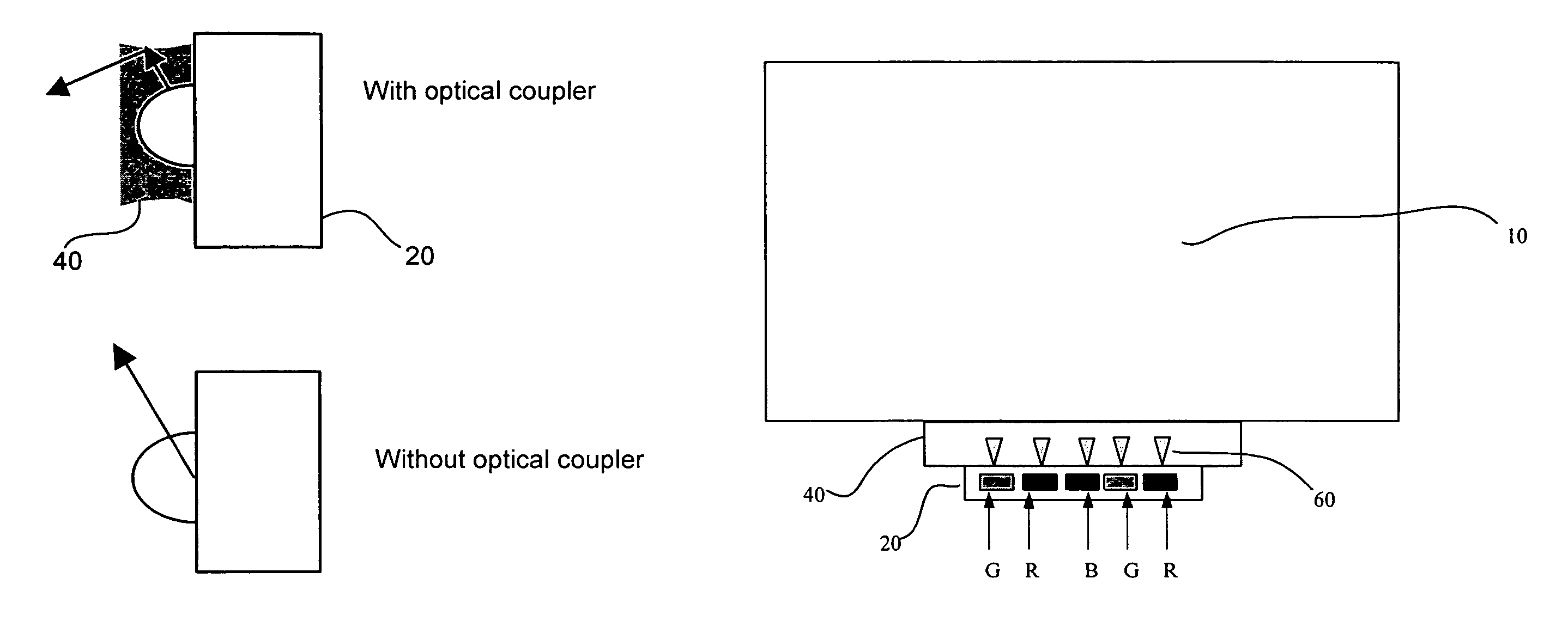
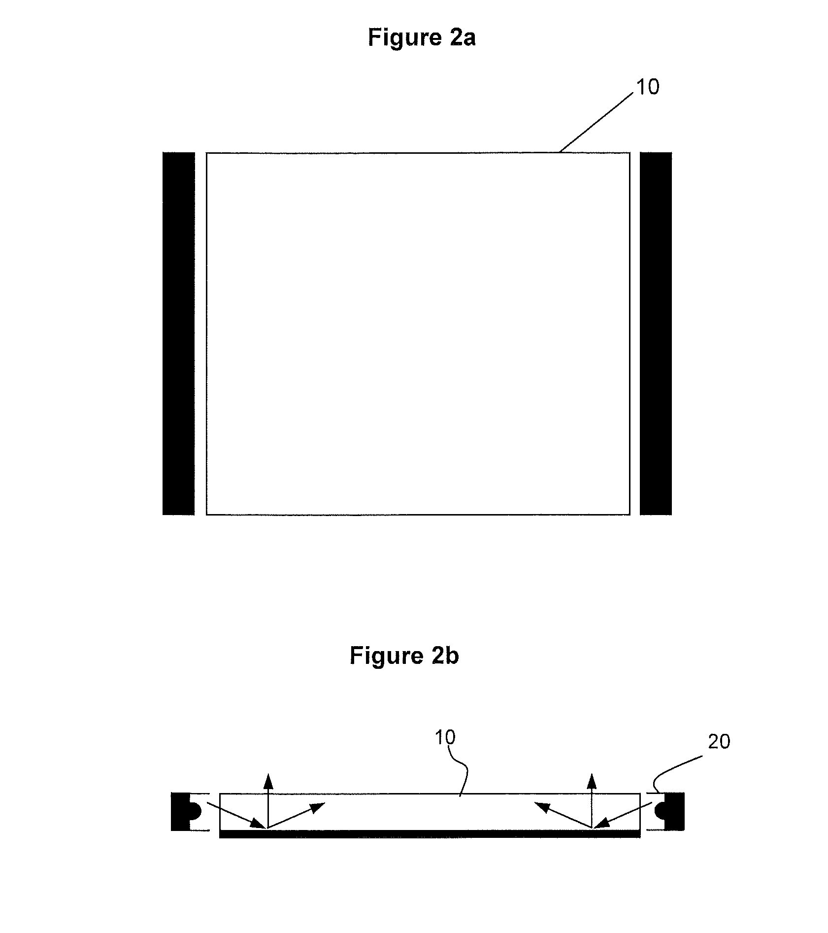
[0027]FIG. 2 shows an exemplary display backlight assembly using a solid state light source (SSLS) 20, according to an embodiment of the present invention. The SSLS 20 according to the embodiment shown in FIG. 2 may include any suitable solid state light source, such as, for example, light emitting diodes (LEDs), solid state lasers, or other suitable semi-conductor-based light source. Furthermore, the SSLS 20 may include one or more resonant cavity light emitting diodes (RCLED), one or more super luminescent light emitting diodes (SLEDs), or one or more organic LEDs. One having ordinary skill in the art will appreciate that the SSLS 20 may include multiple devices (i.e., multiple LEDs) and may include devices that emit light at multiple wavelengths (i.e., a multi-colored array of LEDs). For example, a LED-based SSLS 20 may include an array of red LEDs (labeled as “R” in FIGS. 3-6), green LEDs (labeled as “G” in FIGS. 3-6), and blue LEDs (labeled as “B” in FIGS. 3-6).

[0028]FIG. 3 sho...


PUM


Abstract

A display backlight assembly providing improved optical coupling between a solid state light source and a display optical light guide. The assembly includes an optical coupler to couple the solid state light source and display optical light guide together. In addition, the optical coupler may include a light mixing element for improved mixing of the multi-colored or mono-chromatic light produced by the solid state light source.

Description

CROSS REFERENCE TO RELATED APPLICATION[0001]This application claims the benefit of U.S. Provisional Application Ser. No. 60 / 694,740, filed on Jun. 28, 2005. The entire disclosure of U.S. Provisional Application Ser. No. 60 / 694,740 is incorporated by reference herein.FIELD OF THE INVENTION[0002]The present invention relates to a display backlight assembly providing improved coupling and color mixing. More specifically, the present invention relates to a device providing improved coupling and mixing of multi-colored and mono-chromatic light produced by one or more solid state light sources, such as, for example, light emitting diodes (LEDs), such as a resonant cavity light emitting diodes (RCLEDs), super luminescent light emitting diodes (SLEDs), or organic LEDs.BACKGROUND OF THE INVENTION[0003]Display technology used in many television and computer applications typically uses a backlight panel or plate for illumination of a display, particularly a liquid crystal display (LCD). For ex...

Claims


Application Information

Patent Timeline
Patent Type & Authority Patents(United States)
IPC IPC(8): H01R33/00
CPCG02B6/0021G02B6/0028G02B6/0068
Inventor BAILEY, EDWARDMAZZOCHETTE, JOSEPH B.BEREGSZASZI, ANDREWBURDALSKI, ROBERT J
Owner LIGHTING SCI GROUP
Why Eureka
Try Eureka