
Methods and devices for the delivery of therapeutic gases including nitric oxide

a technology of nitric oxide and gas delivery, which is applied in the direction of respirator, bandage, pharmaceutical product form change, etc., can solve the problems of complex approach, complex distribution, management, recovery, and disposal of gas cylinders, and achieves less cumbersome, less complex, and more cost-effective

Active Publication Date: 2011-12-20
BEYOND AIR LTD
View PDF178 Cites 42 Cited by
  • Summary
  • Abstract
  • Description
  • Claims
  • Application Information

AI Technical Summary

Benefits of technology

"The patent text describes devices and methods for delivering therapeutic gases, particularly nitric oxide (gNO), to animals and humans. The devices are simpler, lighter, and more cost-effective than traditional methods using pressurized gas cylinders and delivery piping. The devices can be used to sterilize medical devices, enclosures, and wounds. The technical effects include improved delivery of therapeutic gases and reduced complexity and cost compared to existing methods."

Problems solved by technology

This approach is complicated by the relatively sophisticated electromechanical devices that are required to accurately and safely deliver the gNO.
For example, the use of high pressure cylinders carries penalties of weight and size and requires the safe regulation of pressure down to pressures low enough to be suitable for application to tissues.
Another limitation is that gas cylinders have elaborate distribution, management, recovery, and disposal needs, especially larger cylinders and cylinders that are intended to last for more than one therapy session.
The complexity of this approach, therefore, can be costly.
This approach may be limited by the complexity and cost of manufacturing such polymers.
This approach may be limited by the polymer's potential to absorb the therapeutic gas, the requirement that the operator charge the polymer before use, and the dependence of the subsequent delivery on the surrounding gas concentration, temperature, and other environmental variables.

Method used


Image

  • Methods and devices for the delivery of therapeutic gases including nitric oxide
  • Methods and devices for the delivery of therapeutic gases including nitric oxide
  • Methods and devices for the delivery of therapeutic gases including nitric oxide

Examples


example 1

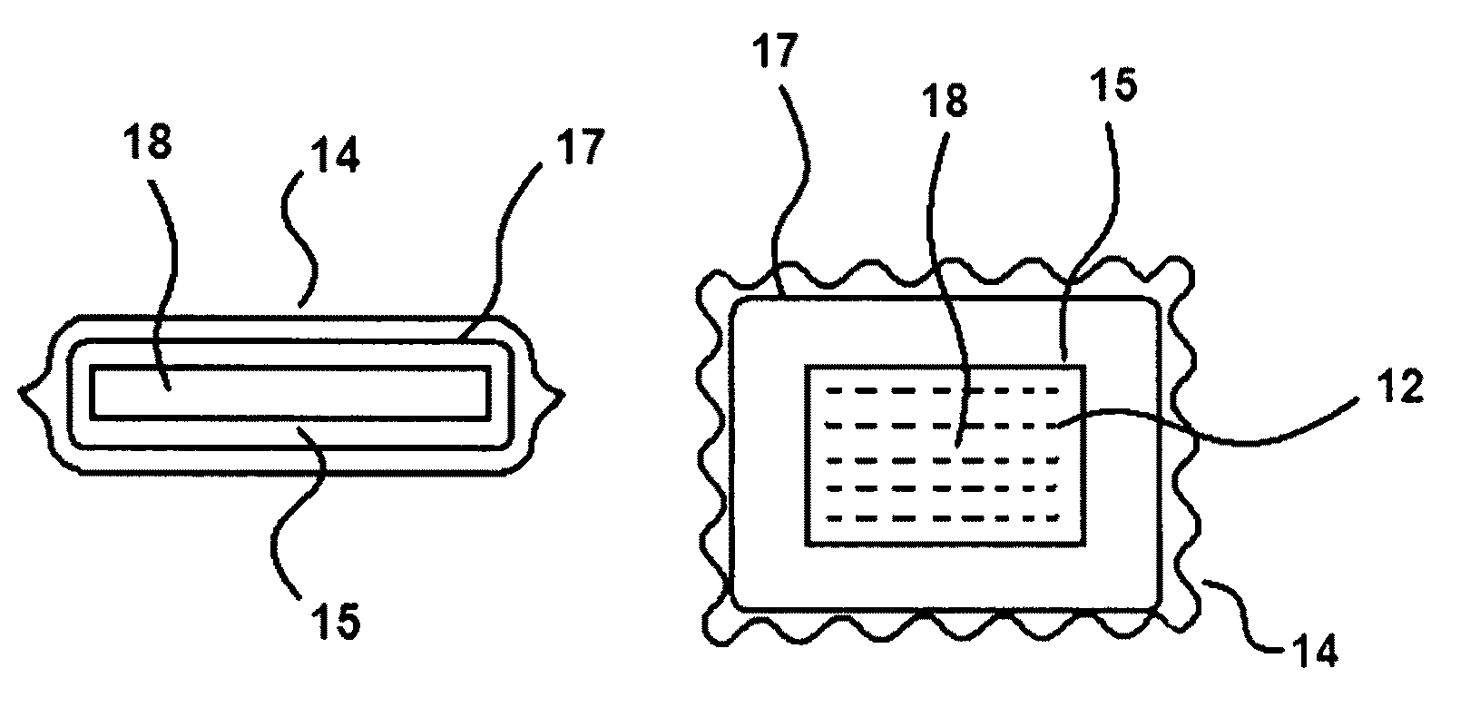
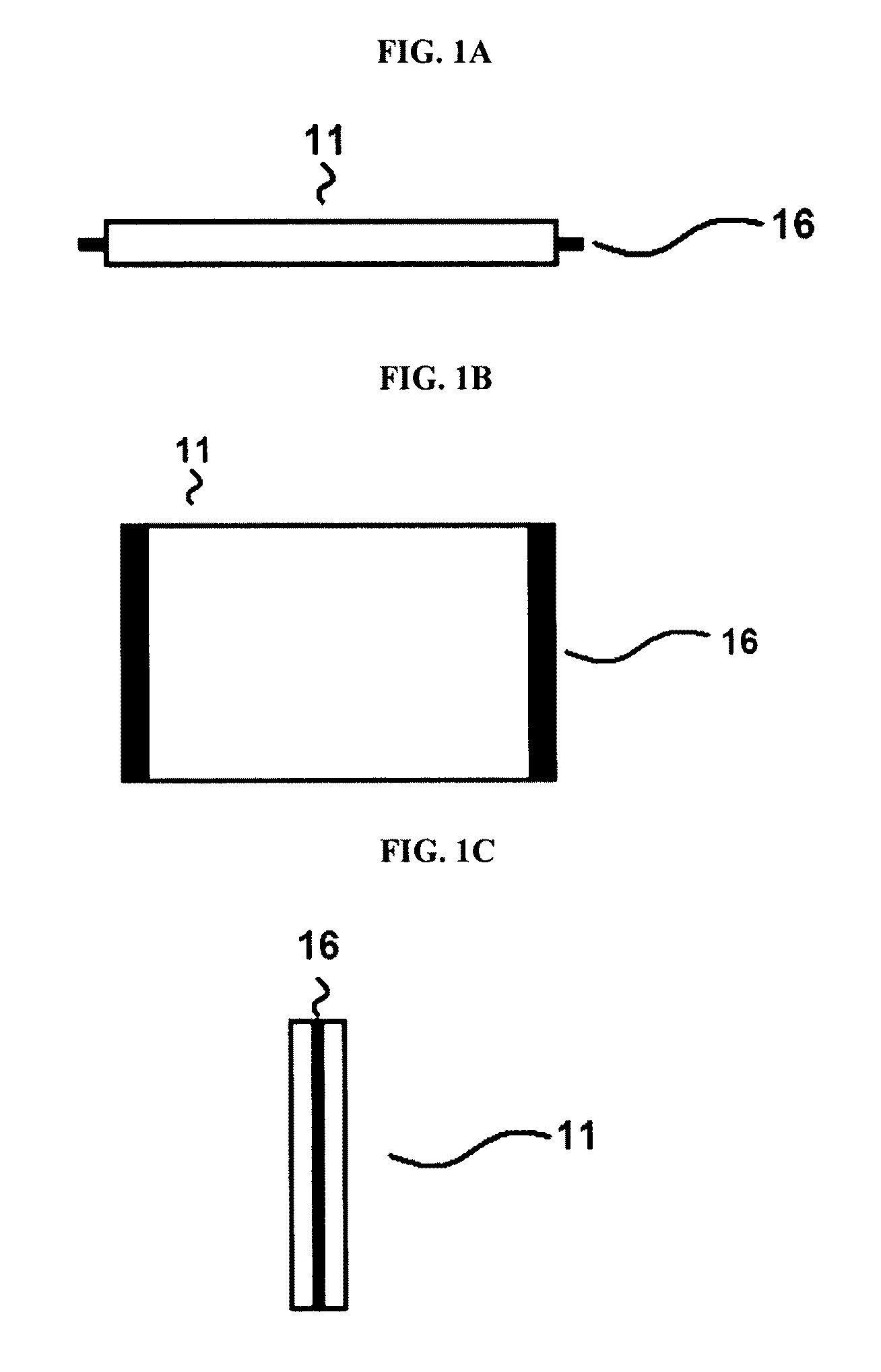
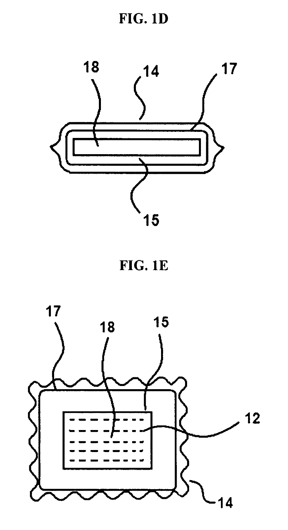
[0070]FIG. 1, embodiments A-G, illustrates an exemplary gas package. Embodiments A-C illustrate, respectively, side, top, and end views of a holding container 11, which is part of the illustrated gas packaged. Embodiments D-F illustrate, respectively, side, top, and end views of the remainder of the device held within the holding container. Embodiment G illustrates an exemplary multi-patch configuration of the device.

[0071]The holding container 11 of the gas package includes optional flange portions 16 on two sides of the container. The flange portions 16 are convenient surfaces by which a user may hold the holding container 11. The holding container preferably is a substantially sealed container for holding the remaining elements of the gas package for long-term storage. The holding container also preferably is rigid and durable so that it is capable of providing a degree of physical protection to its contents.

[0072]The gas package also comprises an interface layer 15 that defines ...

example 2

[0078]FIG. 2, embodiments A-C, are respectively top, front, and end views of a gas package 22 wherein part of the reservoir structure 25 also forms part of the holding container. In this configuration, the interface layer 23 initially is covered by a sealing layer 24 that prevents the outflow or evolution of gas until the sealing layer is removed or compromised in order to expose the interface layer 23, thus activating the gas package 22. Preferably, the sealing layer 24 is secured to the interface layer 23 and reservoir structure 25 by an adhesive that is sufficiently strong to secure the sealing layer 24 but also sufficiently weak to allow the sealing layer to be removed without damaging either the interface layer 23 or reservoir structure 25. In an alternative, the sealing layer 24 or a portion thereof may be intended to be removed by scraping it off of the interface layer 23, for example using a fingernail or coin. As seen in FIG. 2A, the reservoir structures 25 has flanges on e...

example 3

[0079]FIG. 3 is an exemplary plot of the rate of evolution of gas across the interface layer. Prior to activation, the concentration of gas in the gas package is constant since the constituent gas is trapped within the reservoir. When delivery is desired, the impermeable holding container is opened and / or the sealing layer is removed or otherwise compromised and the pressure and / or concentration gradient between the reservoir and the external environment causes gas molecules to migrate across the interface layer, driven by diffusion, permeation, or simply pressure, consistent with the mechanisms of the interface layer that have been described. Activation, indicated by time t(100), typically is the time of the peak gas evolution rate. At some time t(0), the reservoir is substantially exhausted and gas evolution essentially ceases.

[0080]In the intermediate period between times t(100) and t(0), and to a first approximation, the decay in the evolution rate is dominated by an exponential...


PUM


Abstract

Gas packages for the delivery of therapeutic gases, and in particular gaseous nitric oxide (gNO) are provided herein. The gas packages comprise one or more of a gas reservoir, interface layer, sealing layer, and holding container. The interface layer regulates discharge of the therapeutic gas from the gas reservoir to the external environment. The sealing layer and / or holding container prevent evolution of the gas until the sealing layer is compromised or the holding container is opened. The gas packages and methods for using them are useful for the treatment, alleviation, and prevention of various disease and non-disease, medical and non-medical, conditions in humans and animals.

Description

CLAIM OF PRIORITY[0001]This application claims priority to U.S. Provisional Patent Application Ser. No. 60 / 853,103, filed on Oct. 20, 2006, which is expressly incorporated herein by reference in its entirety.FIELD OF THE INVENTION[0002]The invention generally relates to methods and devices for the delivery of therapeutic gases. The therapeutic gases, for example, may be delivered to situs on or in animal and human bodies and elsewhere. More particularly, the invention relates to methods and devices for delivering gaseous nitric oxide (gNO) to situs on or in animal and human bodies. The methods and devices may be useful to treat a variety of medical and non-medical conditions and impart other desirable effects, such as sterilization, that are caused by the delivery of gNO or other gases to animal and human tissues.BACKGROUND OF THE INVENTION[0003]Therapeutic gases may be applied to the body for the purpose of treating a variety of medical and non-medical conditions and producing othe...

Claims


Application Information

Patent Timeline
Patent Type & Authority Patents(United States)
IPC IPC(8): A61M31/00
CPCA61F13/02A61F13/8405A61K9/7007A61K33/00A61L2/0094A61L15/44A61M16/105A61M16/12A61F2013/00646A61F2013/0091A61J3/08A61L2300/114A61L2300/60A61M16/208A61M2202/0275A61F13/0226A61M16/1055A61M16/106A61F13/05
Inventor HOLE, DOUGLAS R.FIGLEY, CURTISLEE, ROBERT E.HUDEC, MICHAELROLFSON, ROBERT
Owner BEYOND AIR LTD
Learn More