Cutting insert with a wear-resistant coating scheme exhibiting wear indication and method of making the same

a technology of wear indication and cutting insert, which is applied in the field of wear-resistant coating scheme on cutting inserts, can solve the problems of affecting the overall removal operation of materials

Active Publication Date: 2011-12-20
KENNAMETAL INC
View PDF110 Cites 29 Cited by
  • Summary
  • Abstract
  • Description
  • Claims
  • Application Information

AI Technical Summary

Benefits of technology

[0108]It can be appreciated that the present invention provides an improved coating cutting insert with wear (or usage) indication properties. These properties utilize a color contrast on the wear indicating coating layer, which in the unused condition presents substantially uniform or consistent visual appearance. However, if during usage the wear indicating coating layer is removed to expose the underlying wear-resistant coating layer (e.g., an alumina coating layer), there is a visually perceivable color contrast between the top coating layer and the alumina coating layer to indicate usage or wear. The top coating layer may also visually indicate usage through discoloration caused by thermal oxidation wherein there is a contrast in color between the oxidized top coating layer and the non-oxidized top coating layer. The top coating layer may also visually indicate usage through adherence or build-up of workpiece material on the cutting insert wherein there is a color contrast between the built-up workpiece material and the top coating layer. The operator can thus look at the cutting insert and discern the used cutting edge(s) from the unused cutting edge(s).
[0109]Further, the present invention provides such a cutting insert that exhibits a smooth surface. In addition, the present invention provides a cutting insert that enhances useful tool life, as well as has both wear indication properties and a smooth surface.
[0110]All patents, patent applications, articles and other documents identified herein are hereby incorporated by reference herein. Other embodiments of the invention may be apparent to those skilled in the art from a consideration of the specification or the practice of the invention disclosed herein. It is intended that the specification and any examples set forth herein be considered as illustrative only, with the true spirit and scope of the invention being indicated by the following claims.

Problems solved by technology

It can be detrimental to the overall material removal operation for a used cutting edge to be placed back in service.

Method used


Image

  • Cutting insert with a wear-resistant coating scheme exhibiting wear indication and method of making the same
  • Cutting insert with a wear-resistant coating scheme exhibiting wear indication and method of making the same
  • Cutting insert with a wear-resistant coating scheme exhibiting wear indication and method of making the same

Examples


Embodiment Construction

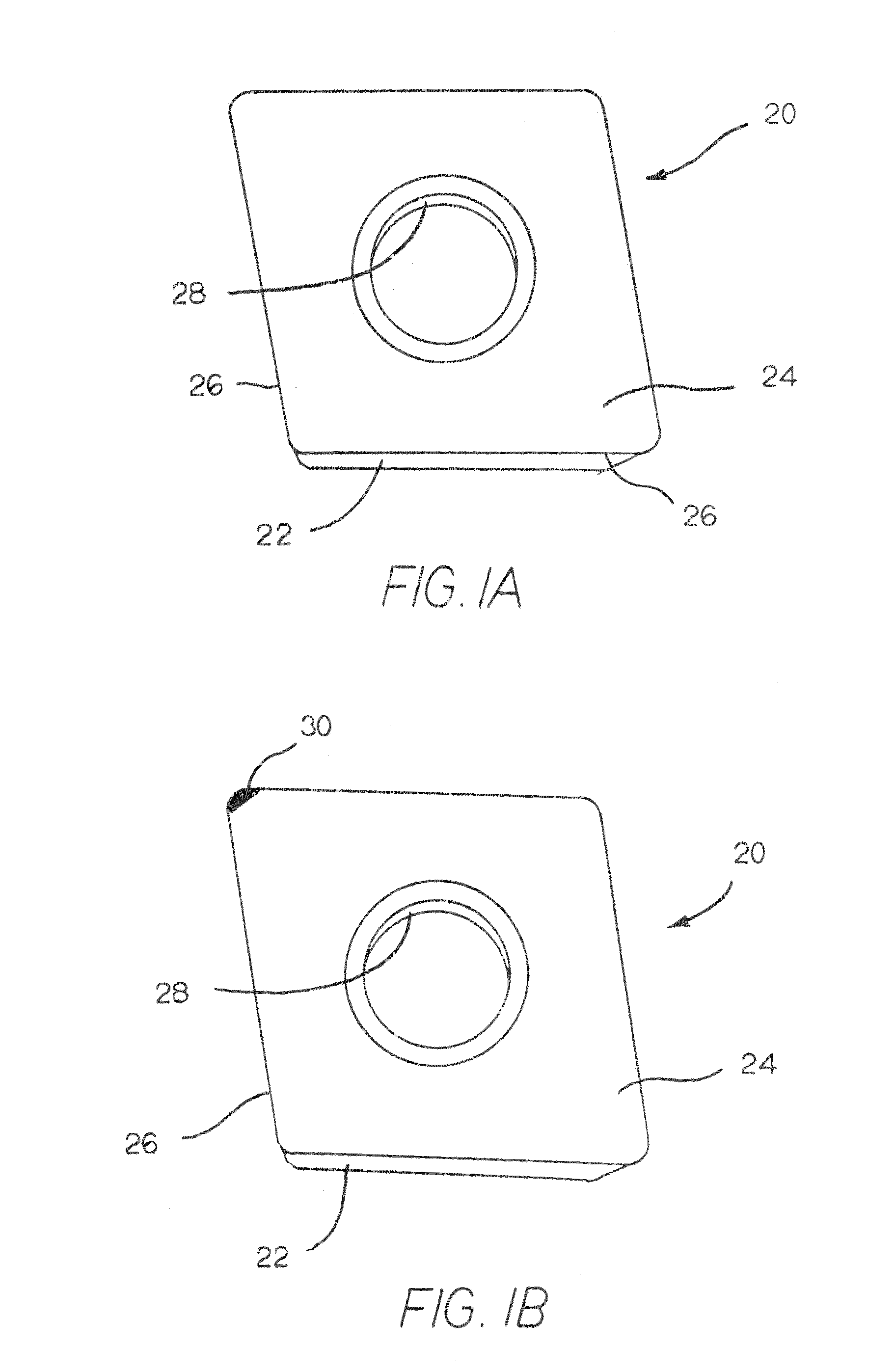
[0047]Referring to FIGS. 1A and 1B, there is illustrated a cutting insert generally designated as 20. Cutting insert 20 is useful in a chip-forming material removal operation wherein the cutting insert removes material from a workpiece. In regard to the structure of the cutting insert, cutting insert 20 has a plurality of flank surfaces 22 and a rake surface 24 wherein there is a cutting edge 26 at the juncture of each flank surface 22 and the rake surface 24. Cutting insert 20 thus presents a plurality of cutting edges. Cutting insert 20 further contains a central aperture 28 useful for attachment of the cutting insert to a holder.

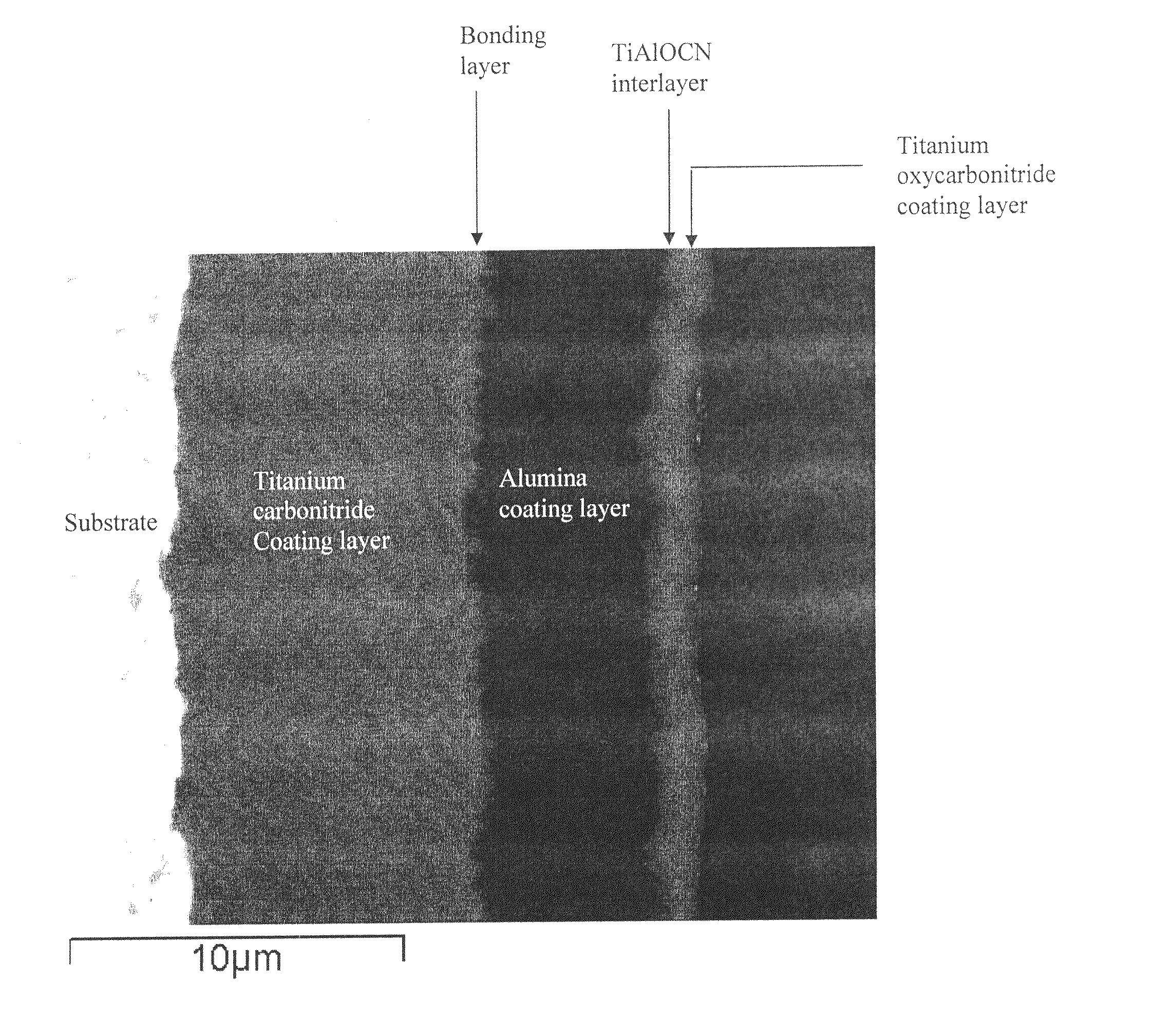
[0048]As mentioned above, the invention pertains to a coated cutting insert 20 with a wear-resistant coating scheme that exhibits wear indication via visually contrasting colors of an outer wear-indicating coating layer that operatively adheres to an alumina coating layer. A comparison of the rake surfaces of the coated cutting inserts illustrated in FIGS...


PUM

PropertyMeasurementUnit
thicknessaaaaaaaaaa
thicknessaaaaaaaaaa
thicknessaaaaaaaaaa

Abstract

A coated cutting insert for use in a chip-forming material removal operation wherein the coated cutting insert includes a substrate that has a flank surface and a rake surface and the flank surface intersects the rake surface to form a cutting edge at the intersection. There is a wear-resistant coating scheme that adheres to at least a portion of the substrate. The wear-resistant coating scheme includes one or more coating layers of one or more of alumina, hafnia and zirconia. There is a wear indicating coating that adheres to at least a portion of the wear-resistant coating scheme. The wear indicating coating includes M(OxCyNz) wherein M is selected from the group comprising one or more of the following titanium, hafnium, zirconium, chromium, titanium-aluminum alloy, hafnium-aluminum alloy, zirconium-aluminum alloy, chromium-aluminum alloy, and their alloys, and x>0, y≧0, z≧0 and y+z>0. A method of making a cutting insert with wear indicating coating including the steps of: providing a substrate with an outer alumina coating layer; applying an as-deposited non-wear indicating coating layer to the alumina coating layer; and treating the non-wear indicating coating layer to convert it to a wear indicating coating layer.

Description

CROSS-REFERENCE TO EARLIER CO-PENDING PATENT APPLICATION[0001]This patent application is a continuation-in-part of earlier-filed and co-pending U.S. patent application Ser. No 11 / 823,679 filed on Jun. 28, 2007 by Zhigang Ban, Mark J. Rowe, Yixiong Liu, and Alfred S. Gates, Jr. for a CUTTING INSERT WITH A WEAR-RESISTANT COATING SCHEME EXHIBITING WEAR INDICATION AND METHOD OF MAKING THE SAME. Applicants (Zhigang Ban, Mark J. Rowe, Yixiong Liu, Alfred S. Gates, Jr., Kent P. Mizgalski and Mark S. Greenfield) claim under the United States Patent Statute (Title 35, United States Code) including 35 U.S.C. §120 the benefit of the filing date of such earlier parent patent application (Ser. No. 11 / 823,679).BACKGROUND OF THE INVENTION[0002]The present invention relates to a coated cutting insert with a wear-resistant coating scheme that exhibits wear indication and a method of making the same. More specifically, the invention pertains to a coated cutting insert with a wear-resistant coating sc...

Claims


Application Information

Patent Timeline
Patent Type & Authority Patents(United States)
IPC IPC(8): B32B9/00
CPCB23B27/141C23C28/044C23C30/005B23B2228/10B23B2260/144Y10T428/265Y10T428/24777Y10T407/27B23B27/14B23P15/28B32B15/00C23C16/00
Inventor BAN, ZHIGANGROWE, MARK J.LIU, YIXIONGGATES, JR., ALFRED S.MIZGALSKI, KENT P.GREENFIELD, MARK S.
Owner KENNAMETAL INC
Why Eureka
Try Eureka