Apparatus for bone density assessment and monitoring

a bone density and apparatus technology, applied in the field of xray systems, can solve the problems of repeated scans, insufficient accuracy of clinical results, and longer patient scan time,

Inactive Publication Date: 2011-12-27
OSTEOMETER MEDITECH
View PDF37 Cites 5 Cited by
  • Summary
  • Abstract
  • Description
  • Claims
  • Application Information

AI Technical Summary

Benefits of technology

[0025]In one embodiment, the at least one detector element pair comprises a low energy detector element and a high energy detector element arranged in a post-collimated stack configuration. Further, the post-collimated stack configuration comprises: a low energy detector element; a copper strip placed underneath the low energy detector element; a high energy detector element positioned underneath the copper strip; and at least one lead piece for post-collimation, positioned adjacent to the high energy detector element, to eliminate scatter radiation from entering into the high energy detector.

Problems solved by technology

While ultrasound methods for determining bone loss condition have been employed in the past, clinical results have shown that they are not adequately accurate.
This requires longer patient scan time, requires patients to maintain a still body position for a longer duration of time and exposes patients to higher radiation dose.
Maintaining a still position for long durations of time becomes difficult for patients and leads to erroneous readings and repeat scans.
In addition, prior art systems tend to be large, bulky, difficult to move, and require large amounts of power.
Also, since the detectors are directly exposed to radiation during each patient scan, the detectors are susceptible to radiation damage.

Method used


Image

  • Apparatus for bone density assessment and monitoring
  • Apparatus for bone density assessment and monitoring
  • Apparatus for bone density assessment and monitoring

Examples


Embodiment Construction

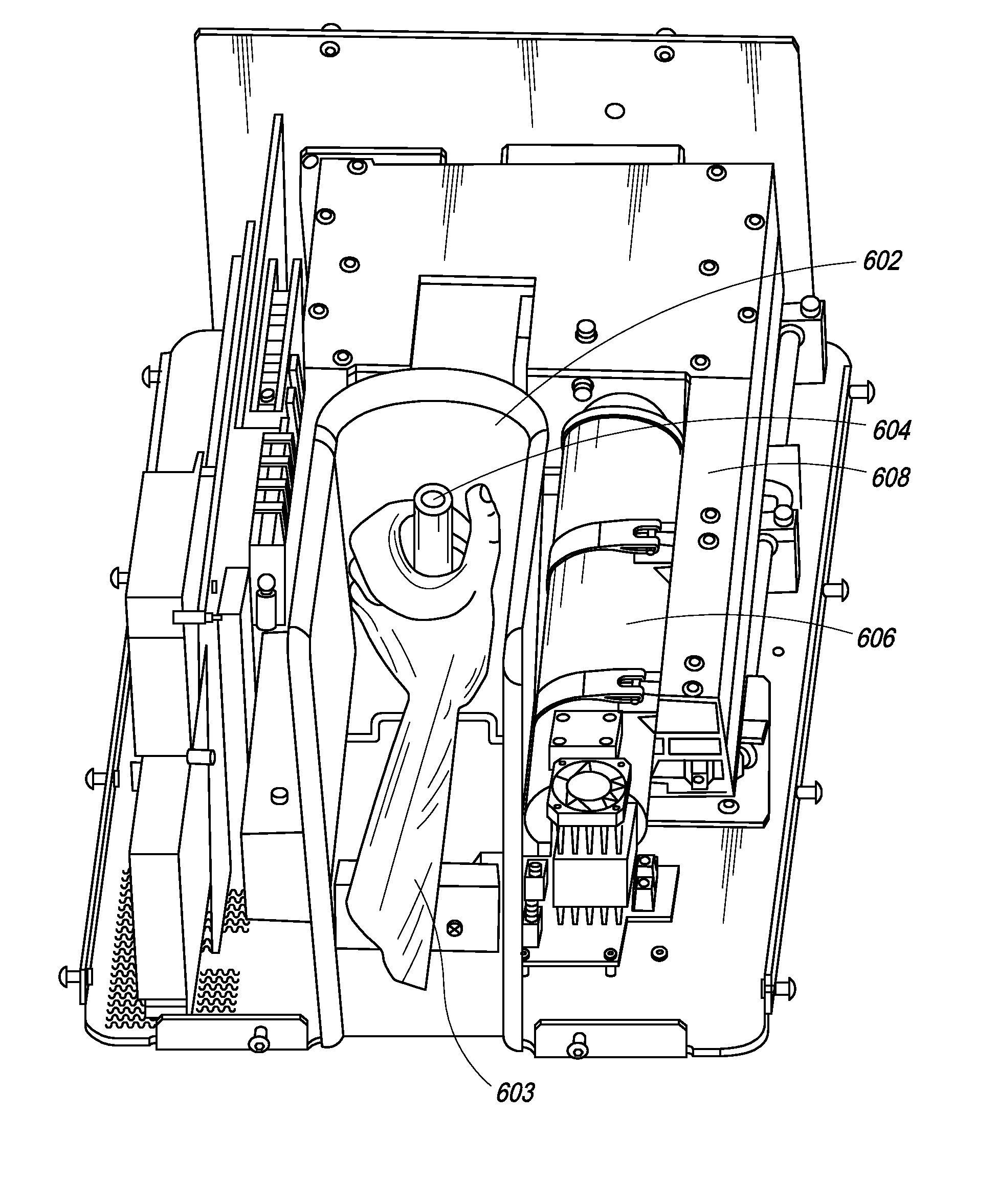
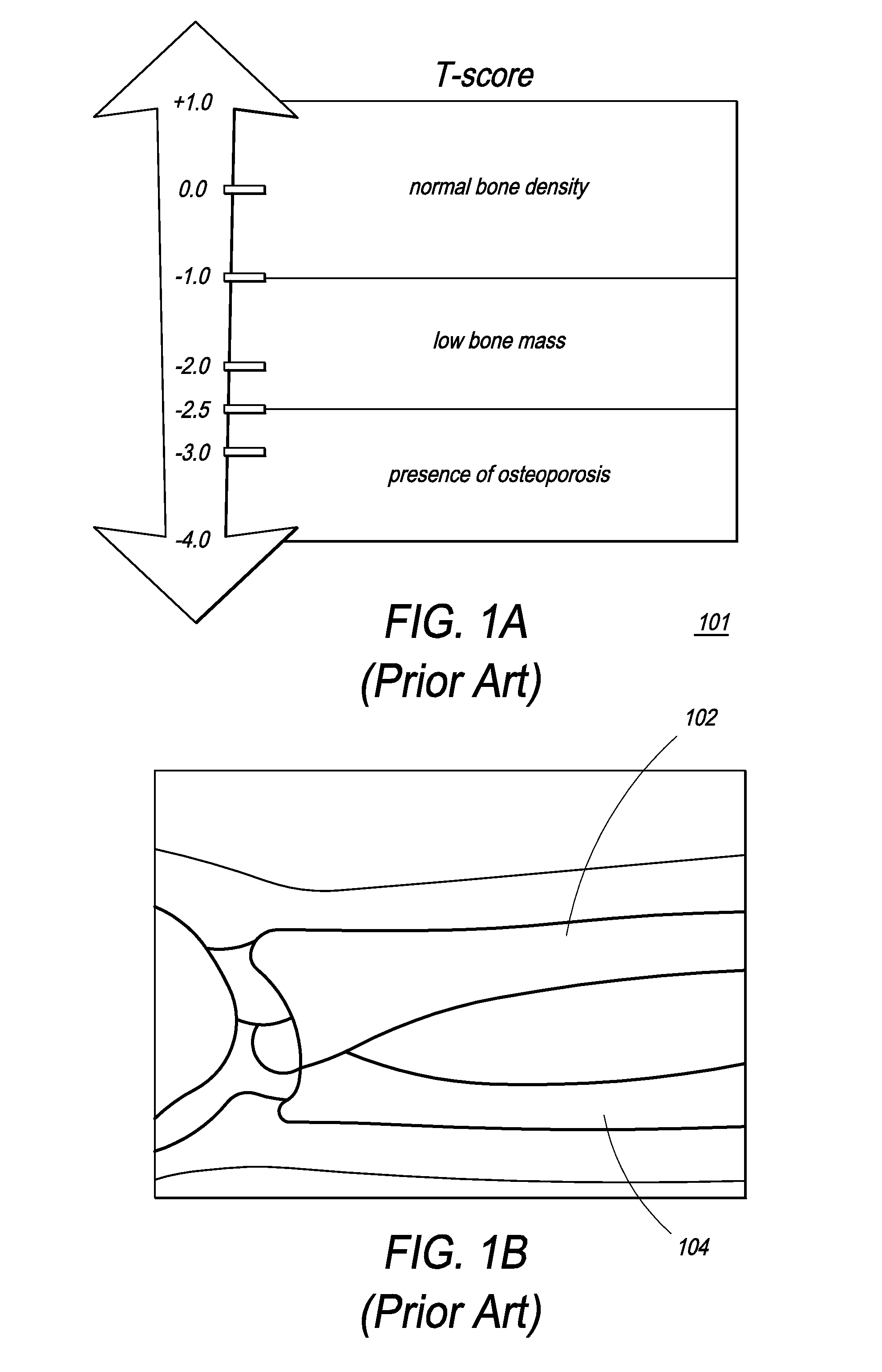
[0079]The present invention is directed towards a dual energy X-ray apparatus for bone density loss assessment and monitoring. A bone densitometry reading of a patient's wrist is taken using the dual energy X-ray apparatus in order to assess bone loss condition. Progression of osteoporosis is monitored by taking repeated readings of the patient's wrist over a period of time, while the patient is undergoing therapy.

[0080]The following disclosure is provided in order to enable a person having ordinary skill in the art to practice the invention. Exemplary embodiments are provided only for illustrative purposes and various modifications will be readily apparent to persons skilled in the art. The terminology and phraseology used is for the purpose of describing exemplary embodiments and should not be considered limiting. Various modifications to the preferred embodiment, disclosed herein, will be readily apparent to those of ordinary skill in the art and the disclosure set forth herein m...


PUM

PropertyMeasurementUnit
currentaaaaaaaaaa
distanceaaaaaaaaaa
distanceaaaaaaaaaa

Abstract

The present invention relates to a dual energy X-ray apparatus and method for osteoporosis assessment and monitoring. The present invention takes a bone densitometry reading of a patient's wrist to assess osteoporosis and monitor bone loss condition by repeat measurements along with therapy. The bone densitometry system has an X-ray source, dual energy detectors, an arm-rest to place the patient's arm, a motion system to move the source-detector gantry along the patient's forearm, and a computer with a database to archive the wrist image, calculate the bone mineral density, maintain a history of patient information, and generate patient history reports.

Description

FIELD OF THE INVENTION[0001]The present invention relates to X-ray systems used for medical diagnostics. More particularly, the present invention relates to an X-ray apparatus used for measurement of bone density for assessment and monitoring of bone loss related conditions such as osteoporosis.BACKGROUND OF THE INVENTION[0002]X-ray systems are used for medical, industrial and security inspection purposes because they can cost-effectively generate images of internal spaces not visible to the human eye. Materials exposed to X-ray radiation absorb the radiation differently and, therefore, attenuate an X-ray beam to varying degrees, resulting in a transmitted level of radiation that is characteristic of the material. The attenuated radiation can be used to generate a useful depiction of the contents of the irradiated object. The absorption of X-rays is measured by detectors after the beam has passed through the object and an image is produced of its contents and presented to an operato...

Claims


Application Information

Patent Timeline
Patent Type & Authority Patents(United States)
IPC IPC(8): G01N15/02
CPCA61B6/4241A61B6/482A61B6/505G01B15/00
Inventor AGRAWAL, NEERAJALIABADI, MANOOCHER MANSOURIWULFF, CHRISTIANLIM, KAHN-TZE ANDREW
Owner OSTEOMETER MEDITECH
Why Eureka
Try Eureka