Ultrasonic probe deployment device for increased wave transmission and rapid area scan inspections

Active Publication Date: 2012-01-03
NAT TECH & ENG SOLUTIONS OF SANDIA LLC +1
View PDF15 Cites 72 Cited by
  • Summary
  • Abstract
  • Description
  • Claims
  • Application Information

AI Technical Summary

Benefits of technology

[0012]The present invention overcomes the limitations of the prior art by providing an ultrasonic probe deployment device in which an ultrasound-transmitting liquid forms the portion of the ultrasonic wave path in contact with the surface of the material being inspected (i.e., the inspection surface). A seal constrains flow of the liquid, for exampl

Problems solved by technology

The seal conforms to unevenness in the inspection surface, although

Method used


Image

  • Ultrasonic probe deployment device for increased wave transmission and rapid area scan inspections
  • Ultrasonic probe deployment device for increased wave transmission and rapid area scan inspections
  • Ultrasonic probe deployment device for increased wave transmission and rapid area scan inspections

Examples


Embodiment Construction

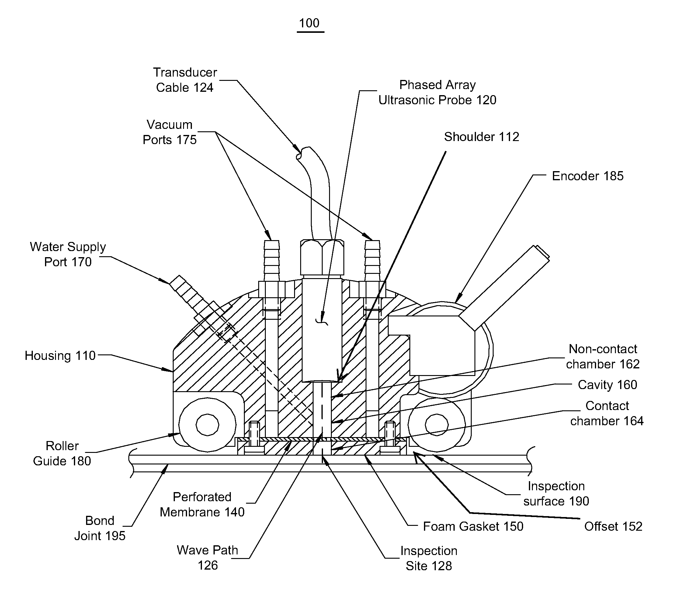
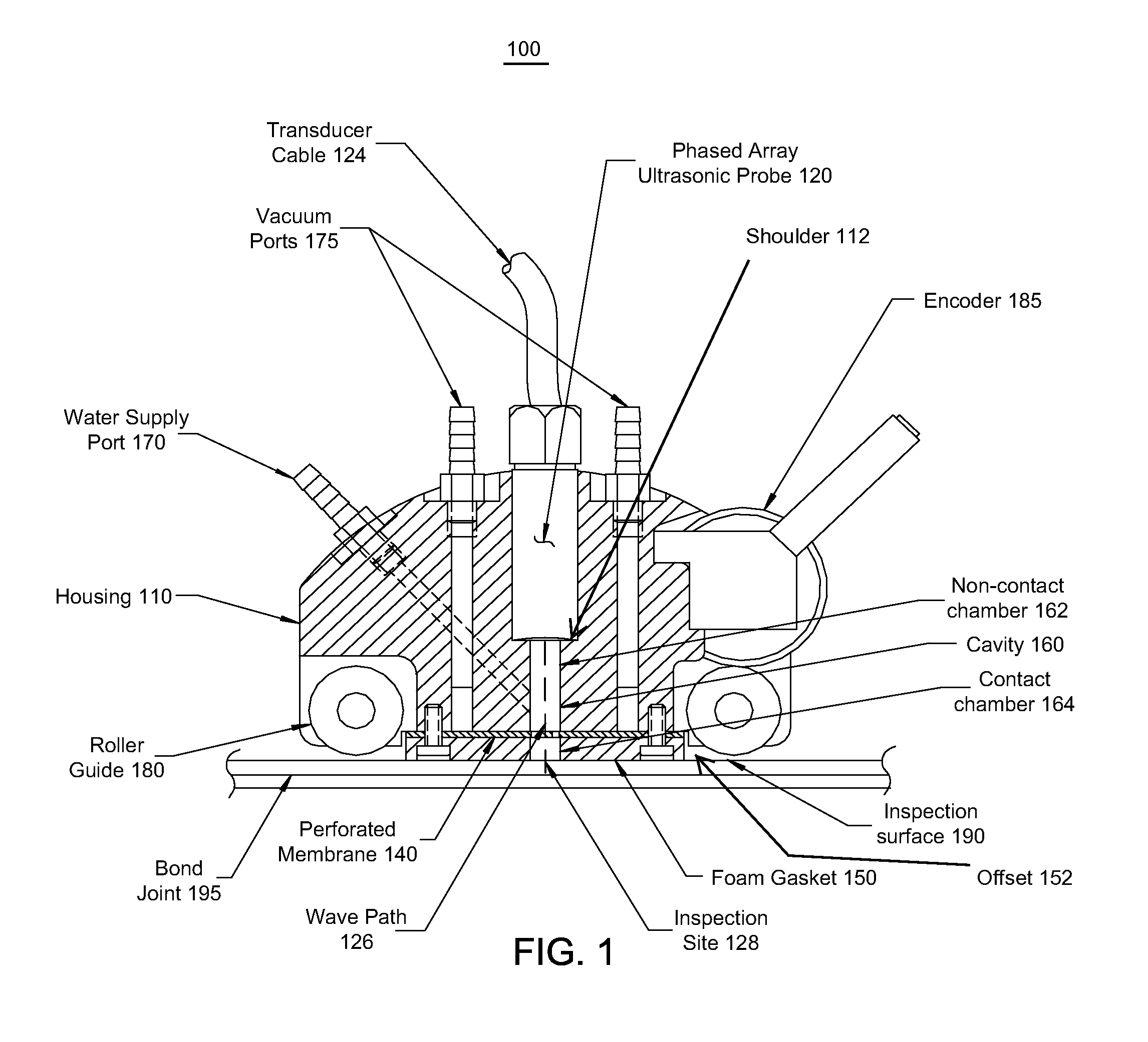
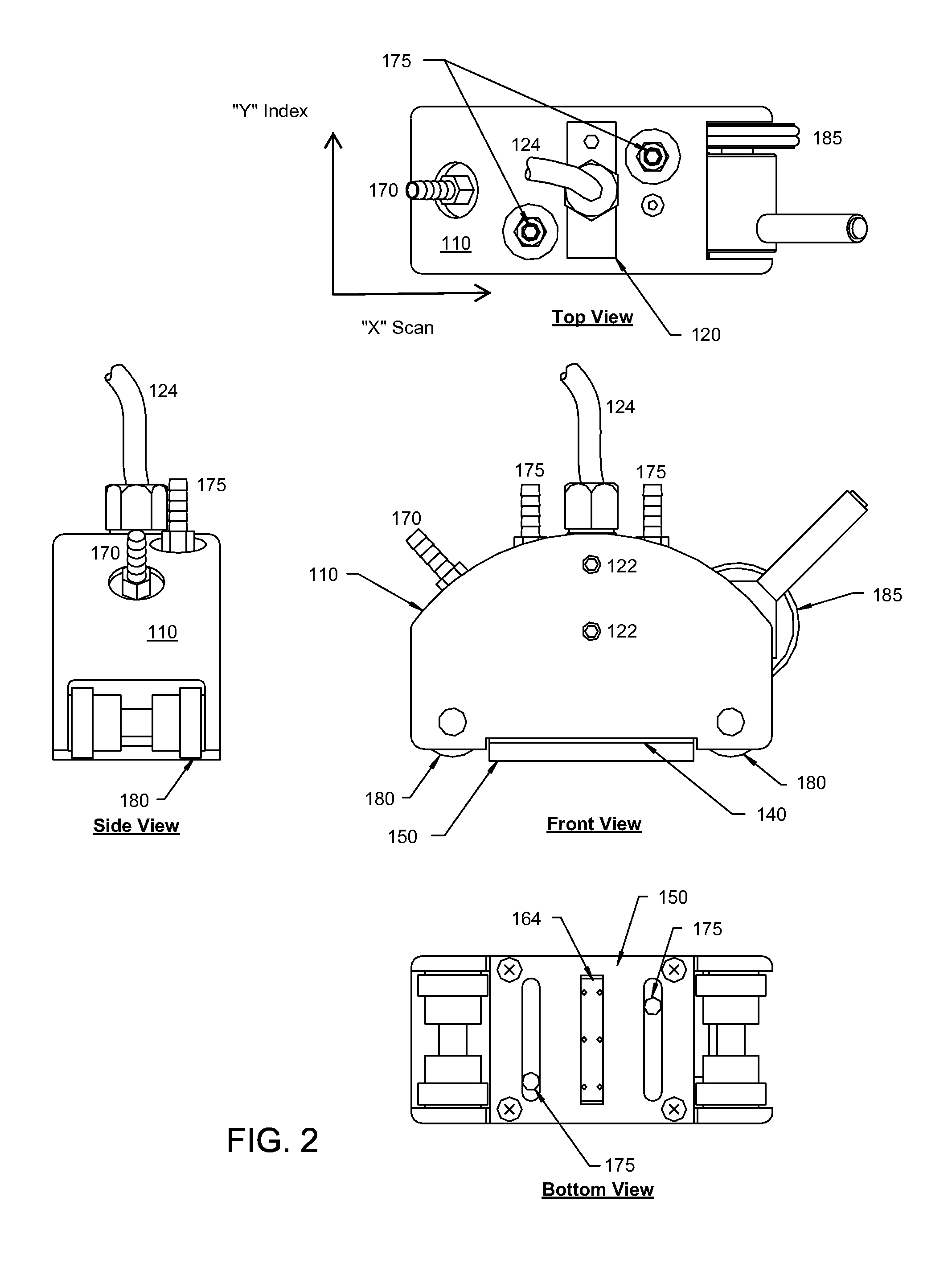
[0031]FIGS. 1-3 are various views of an example ultrasonic probe deployment device 100 according to the invention. The device is used to inspect material, which in this example is a bonded joint 195. The surface of the inspection area shall be referred to as the inspection surface 190. FIG. 1 is a cross-section view. FIG. 2 contains front, top, bottom and side views. FIG. 3 contains bottom views of the foam gasket and perforated membrane.

[0032]An ultrasonic probe 120 rests in a machined recess within the main housing 110 of the probe deployment device 100. Cable 124 is the transducer cable. Two set screws 122 located on each side of the device ensure that the probe 120 remains fixed within the housing 110. The height of the probe 120 can be adjusted vertically depending on the desired focal length of the ultrasonic probe, or (as illustrated) can be adapted to abut a shoulder 112 within the machined recess to set the stand-off distance of the probe to match it's focal length. In this...


PUM


Abstract

An ultrasonic probe deployment device in which an ultrasound-transmitting liquid forms the portion of the ultrasonic wave path in contact with the surface being inspected (i.e., the inspection surface). A seal constrains flow of the liquid, for example preventing the liquid from surging out and flooding the inspection surface. The seal is not rigid and conforms to variations in the shape and unevenness of the inspection surface, thus forming a seal (although possibly a leaky seal) around the liquid. The probe preferably is held in place to produce optimum ultrasonic focus on the area of interest. Use of encoders can facilitate the production of C-scan area maps of the material being inspected.

Description

STATEMENT REGARDING FEDERALLY SPONSORED RESEARCH OR DEVELOPMENT[0001]The United States Government has certain rights in this invention pursuant to Department of Energy Contract No. DE-AC04-94AL85000 with Sandia Corporation.BACKGROUND OF THE INVENTION[0002]1. Field of the Invention[0003]This invention relates generally to ultrasonic inspection of materials, including for example bonded joints that can have uneven surfaces, and narrow joint width.[0004]2. Description of the Related Art[0005]As an example, advances in structural adhesives have permitted engineers to contemplate the use of bonded joints in areas that have long been dominated by mechanical fasteners and welds. The deployment of bonded joints generally requires the use of sensitive nondestructive inspection techniques to ensure the continued integrity of the bond joint.[0006]For example, the use of adhesive bonding in automobile bodies is increasing every year for various reasons. However, current quality control of these...

Claims


Application Information

Patent Timeline
IPC IPC(8): G01N29/24G01N29/28
CPCG01N29/226G01N29/262G01N29/265G01N2291/044
Inventor DIMAMBRO, JOSEPHROACH, DENNIS P.RACKOW, KIRK A.NELSON, CIJI L.DASCH, CAMERON J.MOORE, DAVID G.
Owner NAT TECH & ENG SOLUTIONS OF SANDIA LLC
Why Eureka
Try Eureka