Coupling assembly for connection to a hose

a technology of coupling assembly and hose, which is applied in the direction of hose connection, coupling, manufacturing tools, etc., can solve the problems that the specialized materials that are currently meeting the organoleptic and barrier requirements of beverage hoses do not necessarily work well with the barbs, and premature hose failur

Active Publication Date: 2012-01-10
DANFOSS POWER SOLUTIONS II TECH AS
View PDF26 Cites 29 Cited by
  • Summary
  • Abstract
  • Description
  • Claims
  • Application Information

AI Technical Summary

Benefits of technology

[0003]A coupling assembly includes a fitting having a wall presenting an inner surface, surrounding a lumen, and an outer surface, opposing the inner surface. A barb extends radially away from the outer surface of the wall to a peak. A seal circumferentially surrounds the outer surface of the wall and is spaced from the peak of the barb. A hose has an interior surface surrounding a hollow interior and an exterior surface opposing the interior surface and presenting an initial outer diameter. The wall of the fitting is disposed in the hollow interior of the hose such that the hose extends over each of the seal and the barb so that the hose is deformed at the barb. This presents a displaced outer diameter, proximate the peak of the barb, that is greater than the initial outer diameter of the hose. A cage is spaced at least a distance from the peak of the barb and radially compresses the exterior surface of the hose and the seal. The hose is compressed to present a constricted outer diameter at the cage that is less than each of the initial outer diameter and the displaced outer diameter to form an interference fit between each of the hose, the barb, and the cage. The seal is in sealing engagement with the interior surface of the hose to prevent leakage of fluid from the coupling assembly.
[0004]A method of forming a coupling assembly for a fluid system includes providing a fitting including a wall presenting an outer surface and a barb extending radially away from the outer surface to a peak. A seal is placed circumferentially about the wall of the fitting, in spaced relationship to the barb. A hose, having an initial outer diameter, is placed over each of the barb and the seal such that the hose circumferentially surrounds the wall of the fitting and the hose forms a displaced outer diameter corresponding to the peak of the barb. A cage is placed circumferentially about the hose to radially surround each of the hose and the seal such that the cage is spaced at least a distance away from the peak of the barb. The cage is tightened about the hose to radially compress the exterior surface of the hose and the seal such that the hose is compressed to a constricted outer diameter that is less than each of the initial outer diameter and the displaced outer diameter to form an interference fit between each of the hose, the barb, and the cage. The seal is in sealing engagement with the interior surface of the hose to prevent leakage of fluid from the coupling assembly.
[0005]A coupling assembly includes a fitting having a wall extending between opposing ends and presenting an inner surface, surrounding a lumen and an outer surface opposing the inner surface. A band extends radially from the outer surface to surround the wall such that the wall extends from the band in opposing directions to the respective ends. A barb extends radially away from the outer surface of the wall, proximate each of the ends, to a respective peak. A seal circumferentially surrounds the outer surface of the wall between the band and each of the barbs. Each of a pair of hoses includes an interior surface surrounding a hollow interior and an exterior surface opposing the interior surface, presenting an initial outer diameter. The walls of the fitting are disposed in the hollow interior of a respective one of the hoses such that the respective one of the hoses extends over each of the respective seal and the respective barb such that the respective one of the hoses is deformed at the respective barb to present a displaced outer diameter proximate the respective peak of the respective barb that is greater than the initial outer diameter of the respective one of the hoses. Each of a pair of cages is spaced at least a distance from the peak of the barb and radially compresses each of the exterior surface of the respective hose and the respective seal such that the respective hose is compressed to a present a constricted outer diameter at the respective cage that is less than each of the initial outer diameter and the displaced outer diameter to form an interference fit between each of the respective one of the pair of hoses, the respective barb, and the respective cage. Each of the seals are in sealing engagement with the interior surface of the respective one of the pair of hoses to prevent leakage of fluid from the coupling assembly
[0006]Accordingly, by using a fitting having a barb combined with a seal, the fitting is able to seal against an inside diameter of the supply hose to prevent the escape of fluid. In addition, by incorporating a cage to surround an outer diameter of the supply hose, a precise cage location of the supply hose to the fitting helps to ensure that the sealant point for the hose / fitting interface is directly located over the compressible o-ring, while preventing the barb from embedding into the hose.

Problems solved by technology

The highly specialized materials that are currently meeting organoleptic and barrier requirements of the beverage hoses do not necessarily work well with the barbs on the fittings because stresses are imparted at the barb / liner interface.
These stress points may lead to premature hose failure as a result of the barbs cutting through the liner, i.e., “delamination”, allowing the flavor to cross-over into the hose.

Method used


Image

  • Coupling assembly for connection to a hose
  • Coupling assembly for connection to a hose
  • Coupling assembly for connection to a hose

Examples


Embodiment Construction

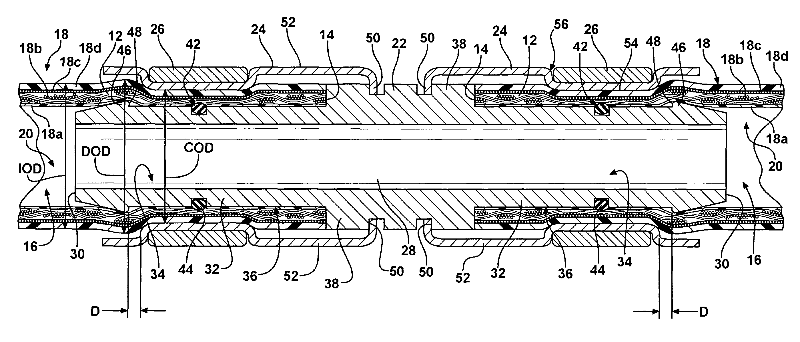
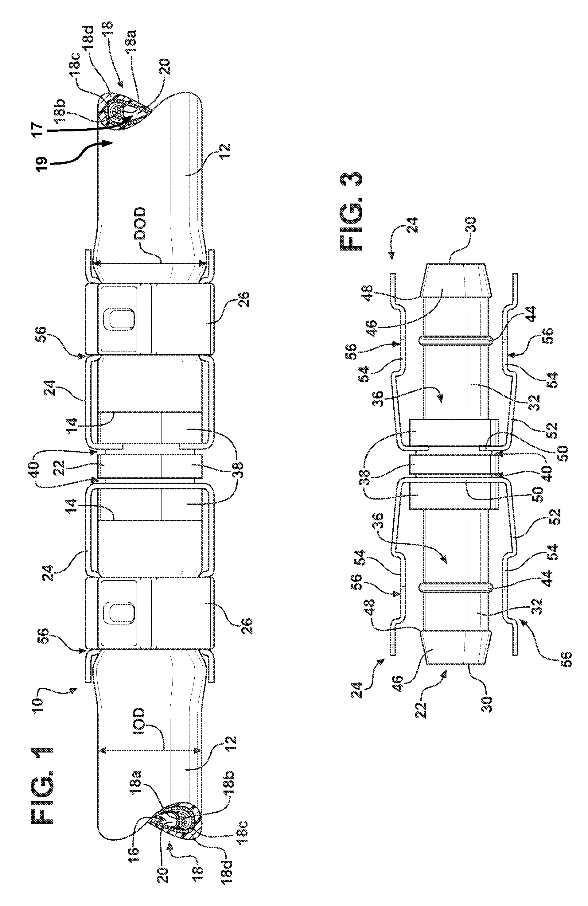
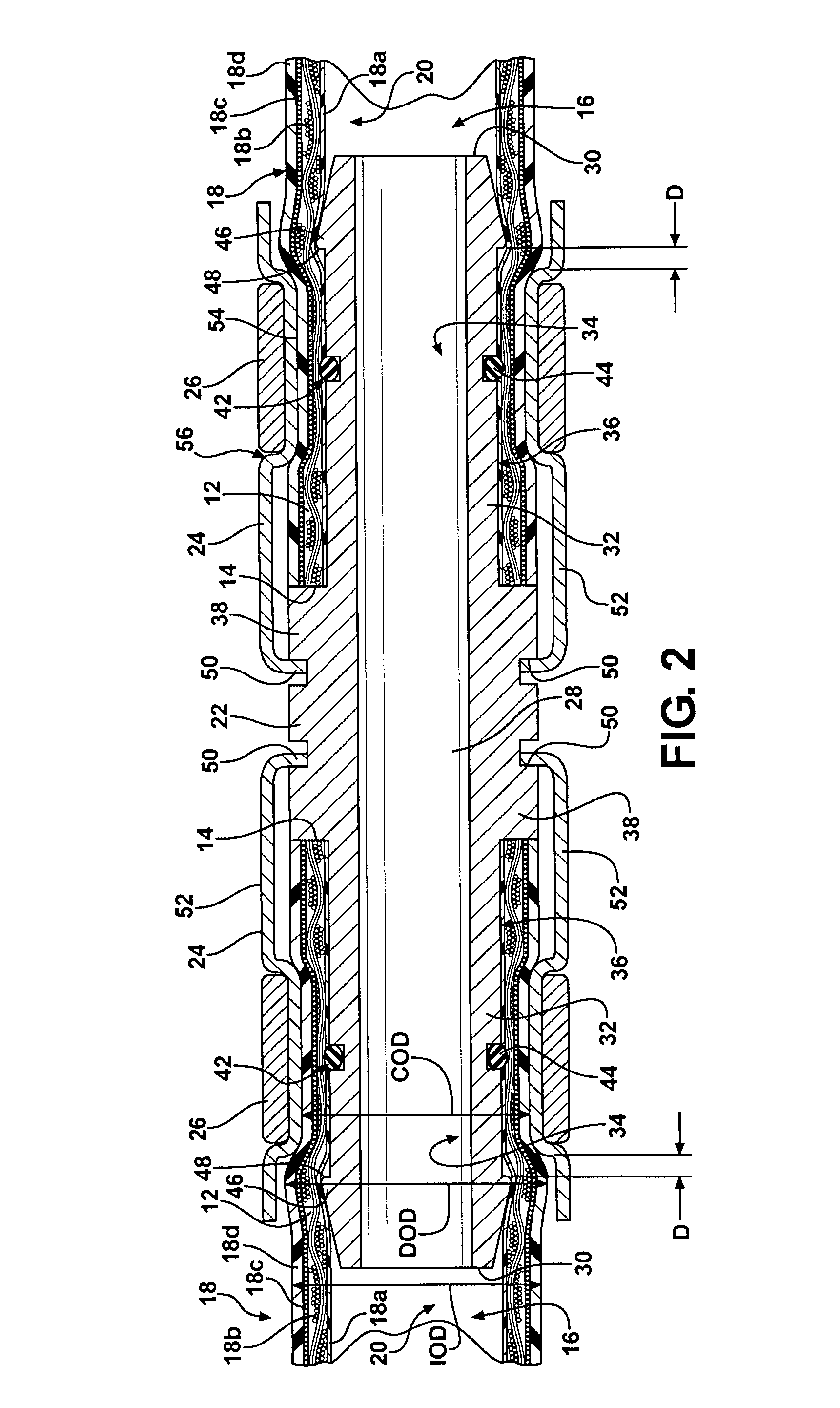
[0022]Referring to the drawings, wherein like reference numbers refer to like components, FIG. 1 shows a coupling assembly 10 interconnecting a pair of hoses 12. The coupling assembly 10 may be used to couple hoses 12 for the conveyance of fluids within a fluid system (not shown). For example, the fluid system may be a beverage system. It should be appreciated, however, that the coupling assembly 10 is not limited to being used in a beverage system, as the coupling assembly 10 may be used in other fluid conveyance systems known to those skilled in the art. The coupling assembly 10 is configured to interconnect the pair of hoses 12 such that the coupling assembly 10 withstands at least two times a working pressure of the fluid system without leakage.

[0023]The hoses 12 each extend to a terminus 14 and define a hollow interior 16 extending therethrough, as shown in FIG. 2. The hoses 12 may be formed from a material approved for use in the beverage industry and the like. Each hose 12 in...


PUM

PropertyMeasurementUnit
distanceaaaaaaaaaa
outer diameteraaaaaaaaaa
thermoplasticaaaaaaaaaa

Abstract

A coupling assembly includes a fitting having a wall presenting an inner surface, surrounding a lumen, and an outer surface, opposing the inner surface. A barb extends radially away from the outer surface of the wall to a peak. A seal circumferentially surrounds the outer surface of the wall and is spaced from the peak of the barb. A hose presents an initial outer diameter. The hose extends over each of the seal and the barb such that the hose is deformed at the barb to present a displaced outer diameter that is greater than the initial outer diameter of the hose. A cage is spaced at least a distance from the peak of the barb and radially compresses the exterior surface of the hose and the seal to form an interference fit between each of the hose, the barb, and the cage.

Description

TECHNICAL FIELD[0001]The present invention relates to a coupling assembly for connection to a hose.BACKGROUND OF THE INVENTION[0002]Beverage hoses are provided for fluid conveyance. The beverage hoses are typically formed from a plurality of layers of differing materials. A fitting typically interconnects the beverage hoses. The fittings include barbs having larger diameters that are embedded into a liner of the wall of the hose, creating a seal where fluid has no path for escape. With a growing trend in beverage products resorting to more pungent, volatile flavors, the materials of the beverage hoses have been modified to meet the challenges of flavor cross-over, i.e., permeation, and flavor scalping. The highly specialized materials that are currently meeting organoleptic and barrier requirements of the beverage hoses do not necessarily work well with the barbs on the fittings because stresses are imparted at the barb / liner interface. These stress points may lead to premature hose...

Claims


Application Information

Patent Timeline
Patent Type & Authority Patents(United States)
IPC IPC(8): F16L33/00
CPCF16L33/2073Y10T403/75Y10T403/4933F16L33/02
Inventor CARRIER, MICHAEL OWENELLERBROCK, RYAN THOMASGREGRICH, GLENN MARTINLUGINBILL, JILL MARIESCHULTZ, BRETT WILLIAMWELCH, JERRY MICHAEL
Owner DANFOSS POWER SOLUTIONS II TECH AS
Why Eureka
Try Eureka