Method and apparatus for control of inductively coupled power transfer systems

a technology of inductive coupling and power transfer system, which is applied in the direction of power electronics conversion efficiency, emergency protective circuit arrangement, energy industry, etc., can solve the problems of large conduction loss, control of the power transferred to the pick-up, and variation in the frequency of the current in the primary path, so as to improve the effect of one or more disadvantages

Active Publication Date: 2012-01-10
AUCKLAND UNISERVICES LTD
View PDF37 Cites 111 Cited by
  • Summary
  • Abstract
  • Description
  • Claims
  • Application Information

AI Technical Summary

Benefits of technology

[0009]It is an object of the present invention to provide a method of controlling, or apparatus for, an ICPT power supply which will ameliorate one or more of the disadvantages suffered by existing systems, or which will at least provide the public with a useful alternative.

Problems solved by technology

A problem with existing ICPT systems is control of the power transferred to pick-ups when they are lightly loaded, for example when a motor is supplied by a pick-up and is idle while it awaits a command from a control system.
However, although that specification addresses the control problem of lightly loaded pick-ups, the shorting switch causes large conduction losses, especially at light loads because it is nearly always conducting in light load conditions.
Another problem with ICPT systems is variation in the frequency of the current in the primary path.
Frequency drift can cause the primary path current to fluctuate which causes problems with control of power transferred to the pick-ups.
More importantly, frequency drift can significantly affect the tuning of pick-ups, especially those that use fixed frequency tuning.
This reduces the ability of the system to effectively transfer power.
This has disadvantages in high Q systems because many capacitors are required.
Also, load variations have to be limited to make the system function effectively.
This is expensive and such power supplies are not suited to miniaturisation.

Method used


Image

  • Method and apparatus for control of inductively coupled power transfer systems
  • Method and apparatus for control of inductively coupled power transfer systems
  • Method and apparatus for control of inductively coupled power transfer systems

Examples


Embodiment Construction

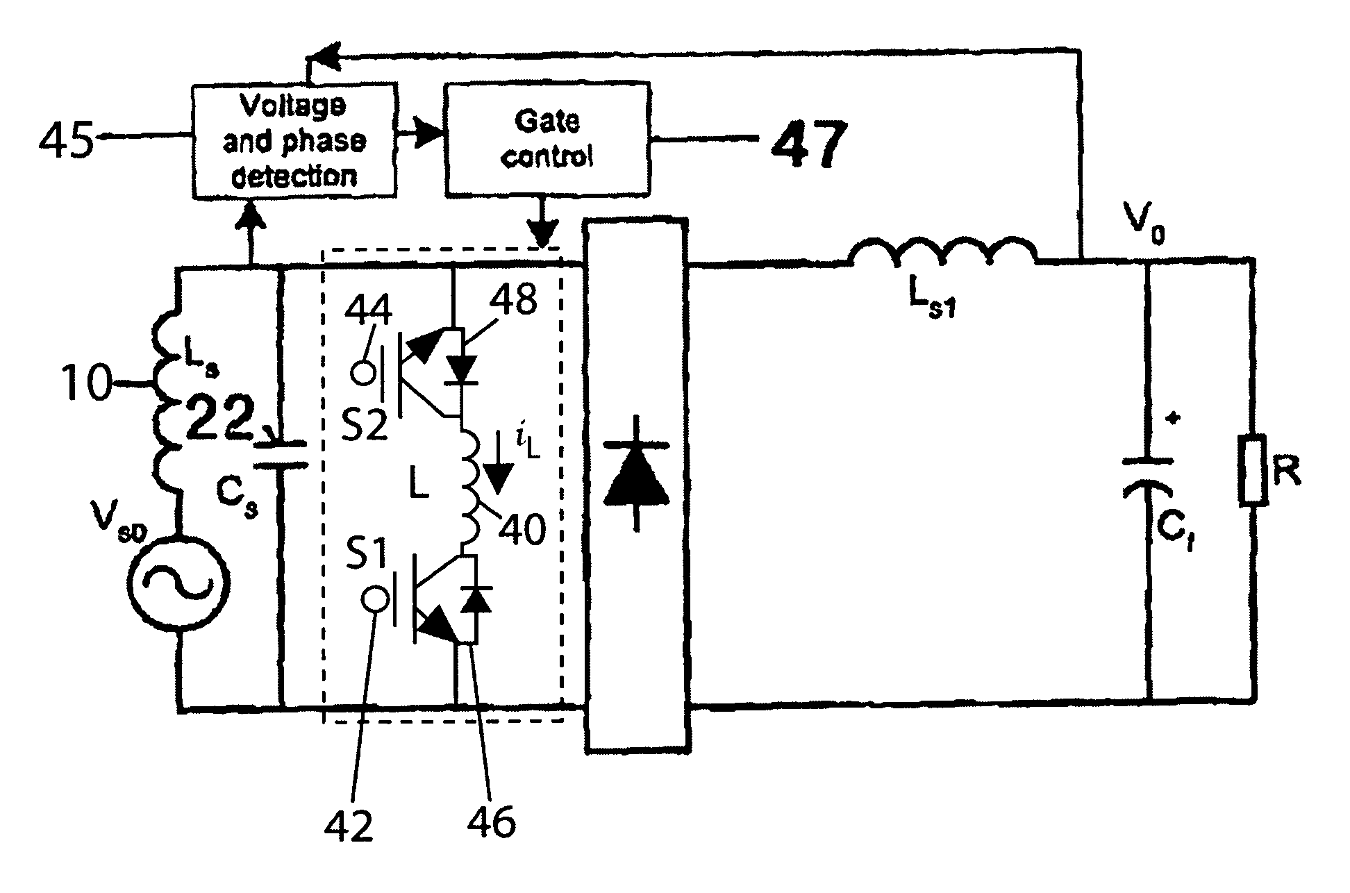
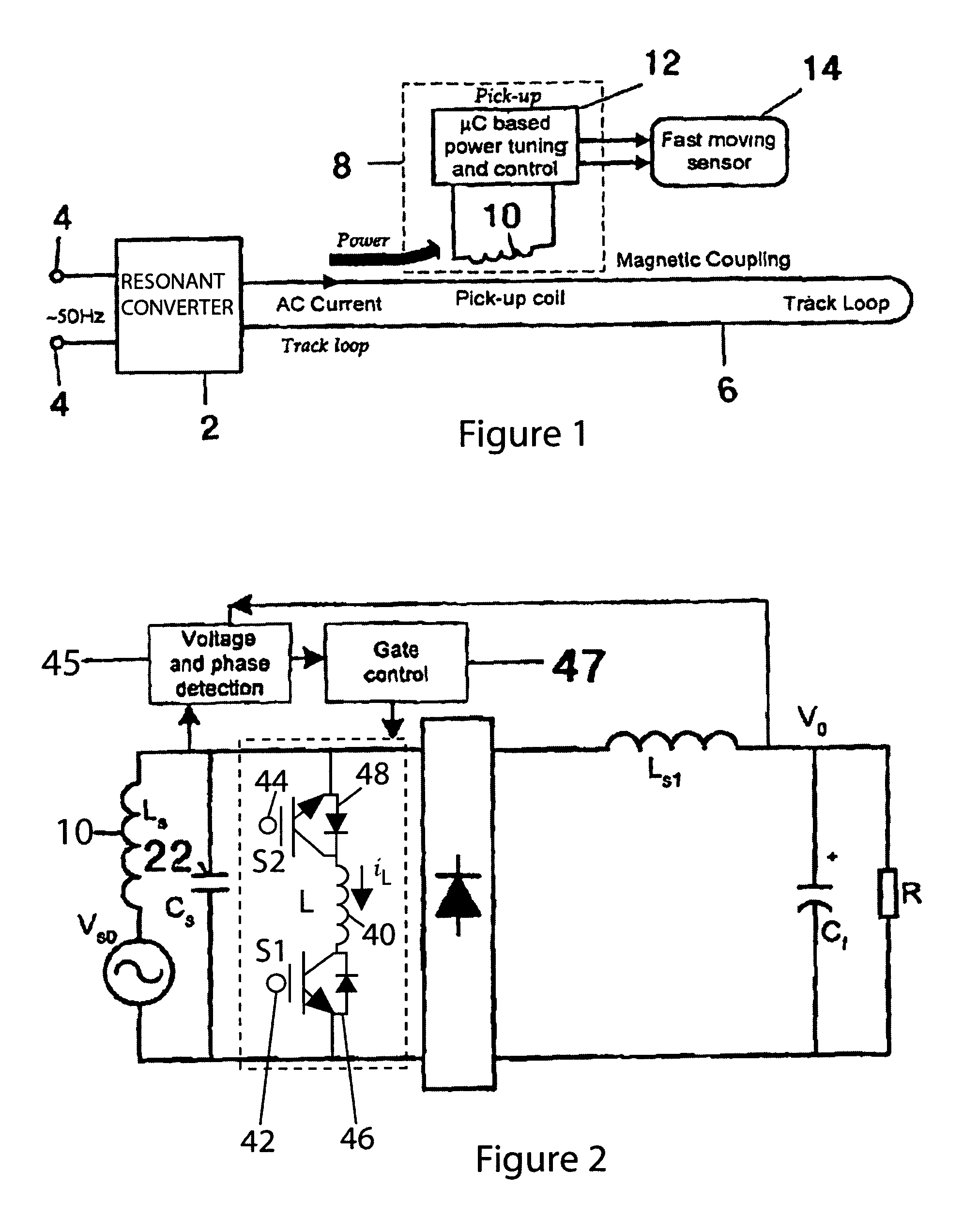
[0048]Referring to FIG. 1, the basic structure of an ICPT power supply (also known as a contactless power supply) system is shown. The system generally comprises two electrically isolated parts. The first part consists of a power supply such as a resonant converter 2 which has inputs 4) for connection to a source of electrical energy, in this example the inputs 4 may be connected to a 50 Hertz mains supply. The first part also includes a primary conductive path 6 which is supplied with alternating current from the resonant converter 2. The primary conductive path 6 is usually in the form of an elongated “track” along which one or more of the second parts are located. In this example, the main function of the converter is to supply a nominally constant high frequency AC current of about 20 amps rms at 40 kHz with a sinusoidal waveform in the track loop.

[0049]The second part consists of one or more pick-ups 8, each of which includes a pick-up conductive element which is usually in the...


PUM

PropertyMeasurementUnit
frequencyaaaaaaaaaa
voltage dropaaaaaaaaaa
delay angleaaaaaaaaaa

Abstract

A power pick-up for an Inductively Coupled Power Transfer (ICPT) system is provided having a resonant pick up circuit. The natural frequency of the pick-up circuit may be varied by controlling the conductance or capacitance of a variable reactive in the resonant circuit. The load being supplied by the pick-up circuit is sensed, and the effective capacitance or inductance of the variable reactive component is controlled to vary the natural resonant frequency of the pick-up circuit to thereby control the power flow into the pick-up to satisfy the power required by the load.

Description

CROSS REFERENCE TO PRIOR APPLICATION[0001]This is a U.S. National Phase application under 35 U.S.C. §371 of International Patent Application No. PCT / NZ2004 / 000096, filed May 21, 2004, which claims priority to New Zealand Patent No. 529869, filed on Nov. 27, 2003, which claims priority to New Zealand Patent No. 526115, filed May 23, 2003. The International Application was published on Dec. 2, 2004 as WO 2004 / 105208 A1 under PCT Article 21(2).FIELD OF THE INVENTION[0002]This invention relates to Inductively Coupled Power Transfer (ICPT) systems and power pick-ups for such systems.BACKGROUND[0003]ICPT power systems (also known as contactless power supplies) are known to have significant advantages in applications such as the materials handling, lighting and transportation industries. There are many applications in both high and low power systems in which use of these power supplies is advantageous.[0004]ICPT systems have a primary conductive path supplied with alternating current from ...

Claims


Application Information

Patent Timeline
Patent Type & Authority Patents(United States)
IPC IPC(8): H02J3/16H02J1/00H02M7/217
CPCH02J1/00H02J5/005H02M7/217H02J2001/002H02M2001/008H02M2007/4815H02M2007/4818Y02B70/1441H02M3/33523H02J50/12H02J1/002Y02B70/10Y02P80/10H02M1/008H02M7/4818H02M7/4815
Inventor HUSSMANN, STEPHAN HHU, AIGUO
Owner AUCKLAND UNISERVICES LTD
Why Eureka
Try Eureka