AC line voltage conditioner and controller

a line voltage conditioner and controller technology, applied in the direction of electric motor control, electric/dynamo-electric converter starters, dynamo-electric converter control, etc., can solve the problems of system over-design, motor over-design, and actual applied voltage, i.e., the real component of the complex ac voltag

Active Publication Date: 2012-01-10
INT CONTROLS & MEASUREMENT
View PDF15 Cites 27 Cited by
  • Summary
  • Abstract
  • Description
  • Claims
  • Application Information

AI Technical Summary

Benefits of technology

[0011]It is an object of this invention to provide power to an AC load, such as a motor armature, and to regulate a

Problems solved by technology

The motor armature, which is basically an inductive load, may have to face an unfavorable power factor, which means that the actual applied voltage, i.e., the real component of the complex AC voltage, may become unacceptably low.
This means that the system has to be over-designed to meet full load requirements at low voltage.
This means that, according to conventional practice, the motor has to be over-designed by at least 19%.
Consequently, at normal or high line conditions, over 20% of the electric energy is wasted or reflected back towards the power station.
However, the use of PWM can lead to other problems, including winding insulation failure in the motor armature, and high switching losses.
Moreover, the PWM VFD devices do not, per se, boost the voltage.
These c

Method used


Image

  • AC line voltage conditioner and controller
  • AC line voltage conditioner and controller
  • AC line voltage conditioner and controller

Examples


Embodiment Construction

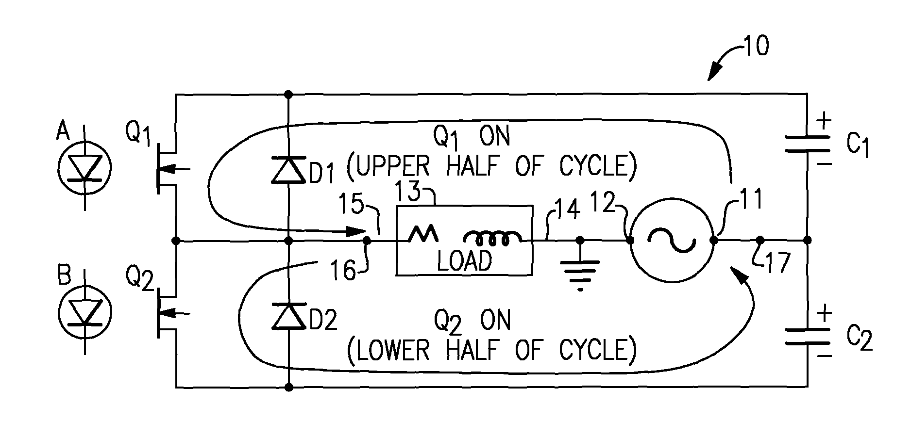
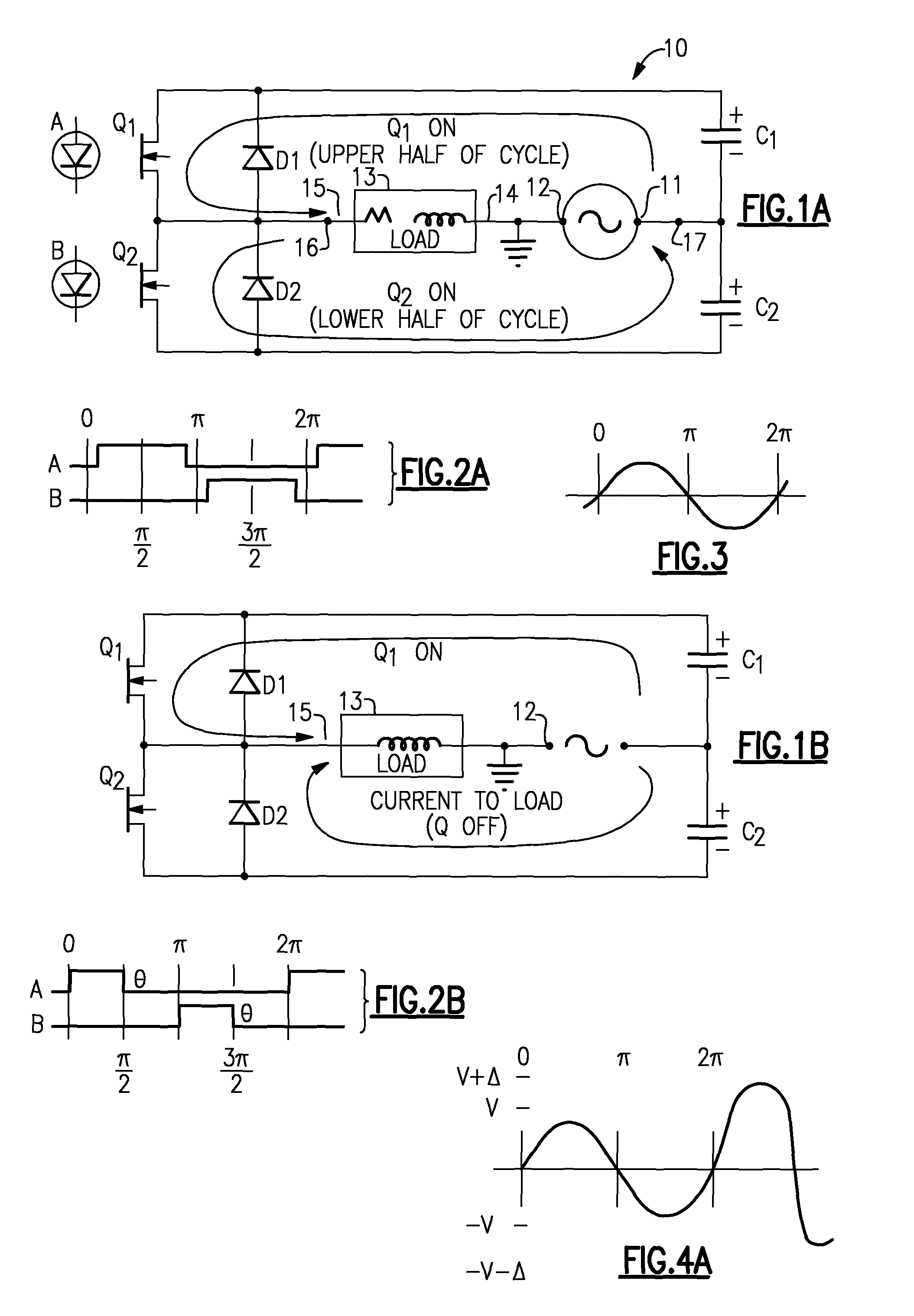
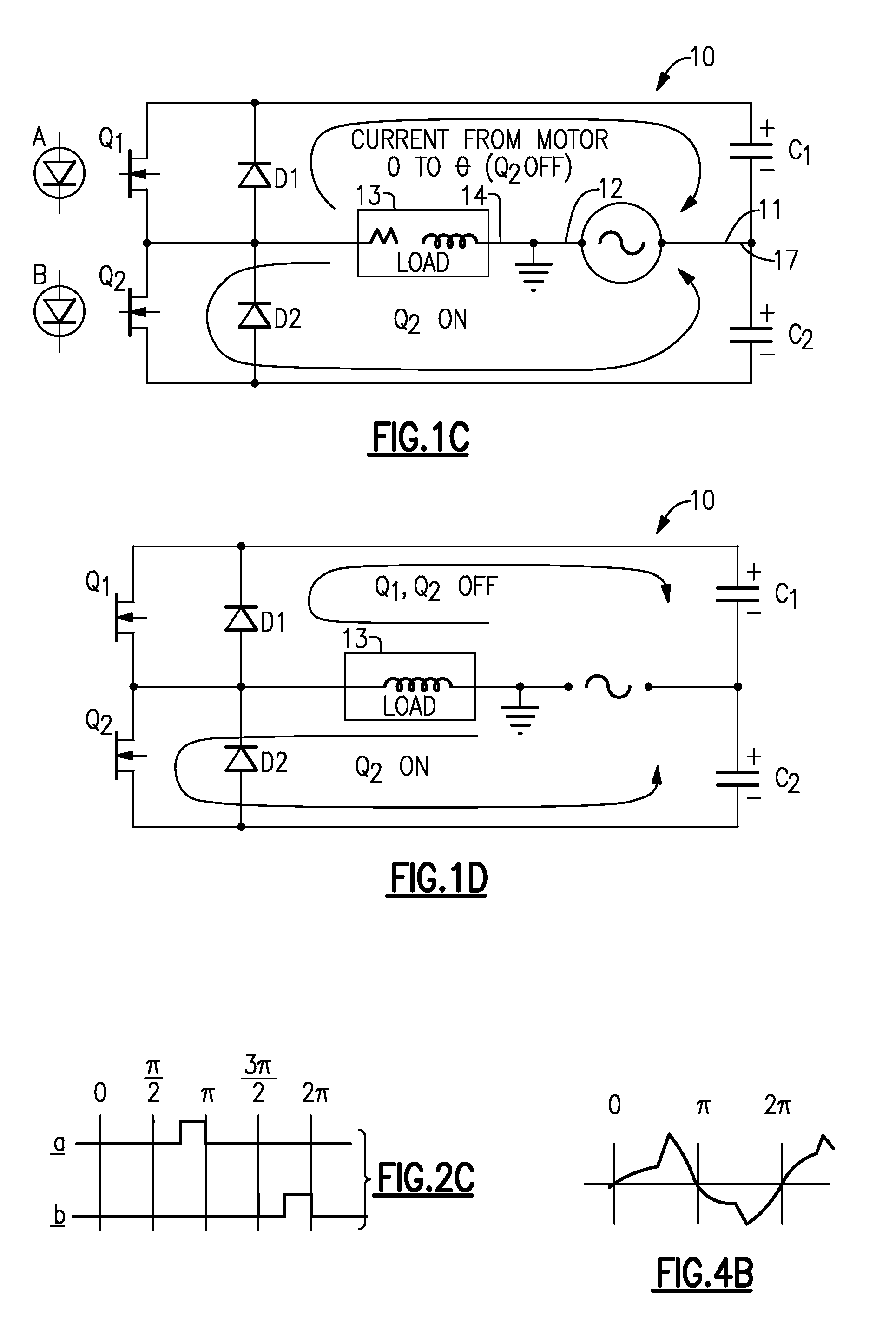
[0062]With reference to the Drawing, FIG. 1A is a basic schematic view of one embodiment of a motor voltage regulating circuit 10 employing the general concepts of this invention, and adapted to receive commercial single-phase AC line power from a source and then conditioning it and applying it to a load. Here, the voltage regulating circuit 10 has AC power inputs 11 and 12. Power input 11 is considered the “hot” or black-wire input and power input 12 is considered the “neutral” or white wire terminal, and is illustrated here as being at ground potential. These are connected to a source of AC line power, represented here by a wave symbol. This can be a source of nominal 117 VAC in North America or 220 VAC in North America or Europe. An AC load device 13, e.g., a single-phase induction motor has a pair of leads 14 and 15, with one lead 14 connected to the AC power terminal 12. The other lead 15 is connected to a terminal 16 of the regulating circuit 10. The “hot” power input 11 is co...


PUM


Abstract

A voltage or power conditioning and control device may be used in line with a source of AC line power and a reactive load such as a single-phase induction motor. The device operates to absorb some of the power reflected by the AC load and generate a synthetic power wave to supplement and correct the applied power in level and phase. The device employs a pair of power capacitors, and a pair of electronic switch devices each with a diode in parallel. Gating or command signals are generated based on the line voltage and timing, e.g., zero crossings. The phase or timing of the command signals is selected for a normal or no-boost mode, a voltage boost mode, or a voltage reduction mode. The capacitors are considered in series with the load, and improve the power factor to the load. A variation of this device may be used in conjunction with a solar array or other local power source.

Description

BACKGROUND OF THE INVENTION[0001]The present invention relates to devices that regulate, condition and control AC power that is provided to an AC load, such as an induction motor. The invention is more specifically directed to an AC power conditioning device that can adjust the wave shape and voltage level of AC power applied to an AC load, as well as power factor and frequency, to compensate for deterioration in quality of the AC line power. The power conditioning device of this invention can be used with motors from fractional horsepower to several horsepower or above, and where the torsional load on the motor may vary depending upon external factors, and in situations where the quality of the line power may drop, i.e., from a nominal 117 VAC (in North America) to below 100 VAC. Also, the device may be employed for controlling the power factor for an AC or inductive load that may vary during use, such as a single-phase AC induction motor, which may be used to drive a compressor in...

Claims


Application Information

Patent Timeline
IPC IPC(8): H02P1/42
CPCH02P1/42H02M5/293H02J2300/24H02J3/381Y02E10/56
Inventor KADAH, HASSAN BKADAH, ANDREW S.
Owner INT CONTROLS & MEASUREMENT
Why Eureka
Try Eureka