Multiple simultaneous context architecture for rebalancing contexts on multithreaded processing cores upon a context change

a context architecture and context technology, applied in multi-programming arrangements, instruments, computations using denominational number representations, etc., can solve the problems of reducing processing throughput, reducing context switching time, and increasing complexity and execution time of graphics processing programs, so as to reduce the need to perform time-consuming context switching and improve graphics processing throughput.

Active Publication Date: 2012-01-10
NVIDIA CORP
View PDF10 Cites 36 Cited by
  • Summary
  • Abstract
  • Description
  • Claims
  • Application Information

AI Technical Summary

Benefits of technology

[0008]Graphics processing elements within a graphics processing system are capable of processing multiple contexts simultaneously, reducing the need to perform time consuming context switches compared to processing multiple contexts serially. Processing elements of a graphics processing pipeline may be configured to support all of the multiple contexts or only a portion of the multiple contexts. Each processing element may be allocated to process a particular context or a portion of the multiple contexts in order to simultaneously process more than one context. The allocation of processing elements to the multiple contexts may be determined dynamically in order to improve graphics processing throughput.

Problems solved by technology

As the capabilities of the graphics processing systems have increased, the complexity and execution time for the graphics processing programs has also increased.
The time needed to unload and load the active state information reduces the processing throughput since the graphics processing system is unavailable during the unloading and loading operations.
When each context requires a small amount of graphics processing, the context switching time may exceed the time spent processing data.
However, some graphic pipelines may be very deep, i.e., have a high latency, and require too long to drain, necessitating a costly active context switch to change to a different context without draining the pipeline.

Method used


Image

  • Multiple simultaneous context architecture for rebalancing contexts on multithreaded processing cores upon a context change
  • Multiple simultaneous context architecture for rebalancing contexts on multithreaded processing cores upon a context change
  • Multiple simultaneous context architecture for rebalancing contexts on multithreaded processing cores upon a context change

Examples


Embodiment Construction

[0025]In the following description, numerous specific details are set forth to provide a more thorough understanding of the present invention. However, it will be apparent to one of skill in the art that the present invention may be practiced without one or more of these specific details. In other instances, well-known features have not been described in order to avoid obscuring the present invention.

System Overview

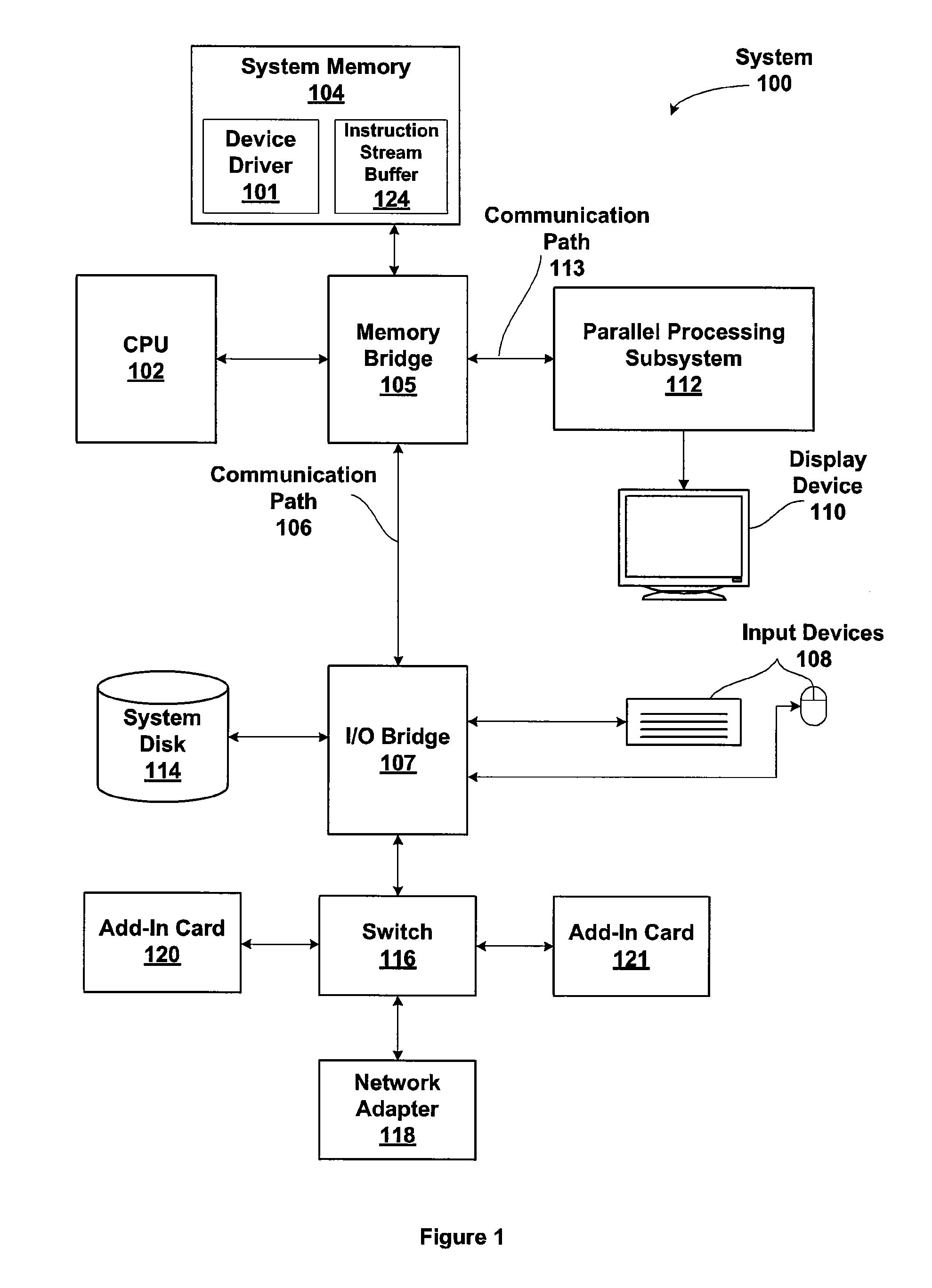
[0026]FIG. 1 is a block diagram illustrating a computer system configured to implement one or more aspects of the present invention. FIG. 1 is a block diagram of a computer system 100 according to an embodiment of the present invention. Computer system 100 includes a central processing unit (CPU) 102 and a system memory 104 communicating via a bus path that includes a memory bridge 105. System memory 104 includes a device driver 101 that is configured to provide an instruction stream buffer 124 that specifies the location of data and program instructions to parallel proce...


PUM


Abstract

Graphics processing elements are capable of processing multiple contexts simultaneously, reducing the need to perform time consuming context switches compared with processing a single context at a time. Processing elements of a graphics processing pipeline may be configured to support all of the multiple contexts or only a portion of the multiple contexts. Each processing element may be allocated to process a particular context or a portion of the multiple contexts in order to simultaneously process more than one context. The allocation of processing elements to the multiple contexts may be determined dynamically in order to improve graphics processing throughput.

Description

CROSS-REFERENCE TO RELATED APPLICATIONS[0001]This application is a continuation-in-part of U.S. patent application titled, “Multiple Simultaneous Context Architecture,” filed Apr. 5, 2007 and having and Ser. No. 11 / 696,928 now U.S. Pat. No. 7,979,683. The aforementioned related patent application is herein incorporated by reference.BACKGROUND OF THE INVENTION[0002]1. Field of the Invention[0003]The present invention generally relates to graphics data processing and more specifically to processing multiple graphics contexts simultaneously and allocating graphics processing units among the multiple graphics contexts.[0004]2. Description of the Related Art[0005]Current graphics processing systems maintain state information for a single processing context. A processing context consists of a complete set of rendering state through the entire graphics pipeline. Many programs running on a CPU will need only one processing context for all their graphics, although some programs might use mul...

Claims


Application Information

Patent Timeline
Patent Type & Authority Patents(United States)
IPC IPC(8): G06F15/00G06F9/00G06F9/44G06F15/76G06F7/38
CPCG06F9/461G06F9/5088
Inventor DANSKIN, JOHN M.SHAH, LACKY V.
Owner NVIDIA CORP
Why Eureka
Try Eureka