
Resonator fiber optic gyroscope (RFOG) with reduced bias error from high order spatial modes

a high-order spatial mode and resonance fiber technology, applied in the direction of speed measurement using gyroscopic effects, instruments, surveying and navigation, etc., can solve the problem that the current low-loss hollow core fiber may weakly support high-order spatial modes, resonance asymmetry that varies, and suppression may be compromised by imperfect spatial, so as to reduce/remove the effect of unwanted modes

Active Publication Date: 2012-01-17
HONEYWELL INT INC
View PDF5 Cites 8 Cited by
  • Summary
  • Abstract
  • Description
  • Claims
  • Application Information

AI Technical Summary

Benefits of technology

[0005]The present invention reduces the impact of the higher order modes on a resonator fiber optic gyroscope (RFOG) bias stability through spatial mode filtering. Round trip losses of the high order spatial modes are increased significantly by spatial mode filters properly placed inside the resonator, leading to very significant reduction of high order mode induced bias errors.
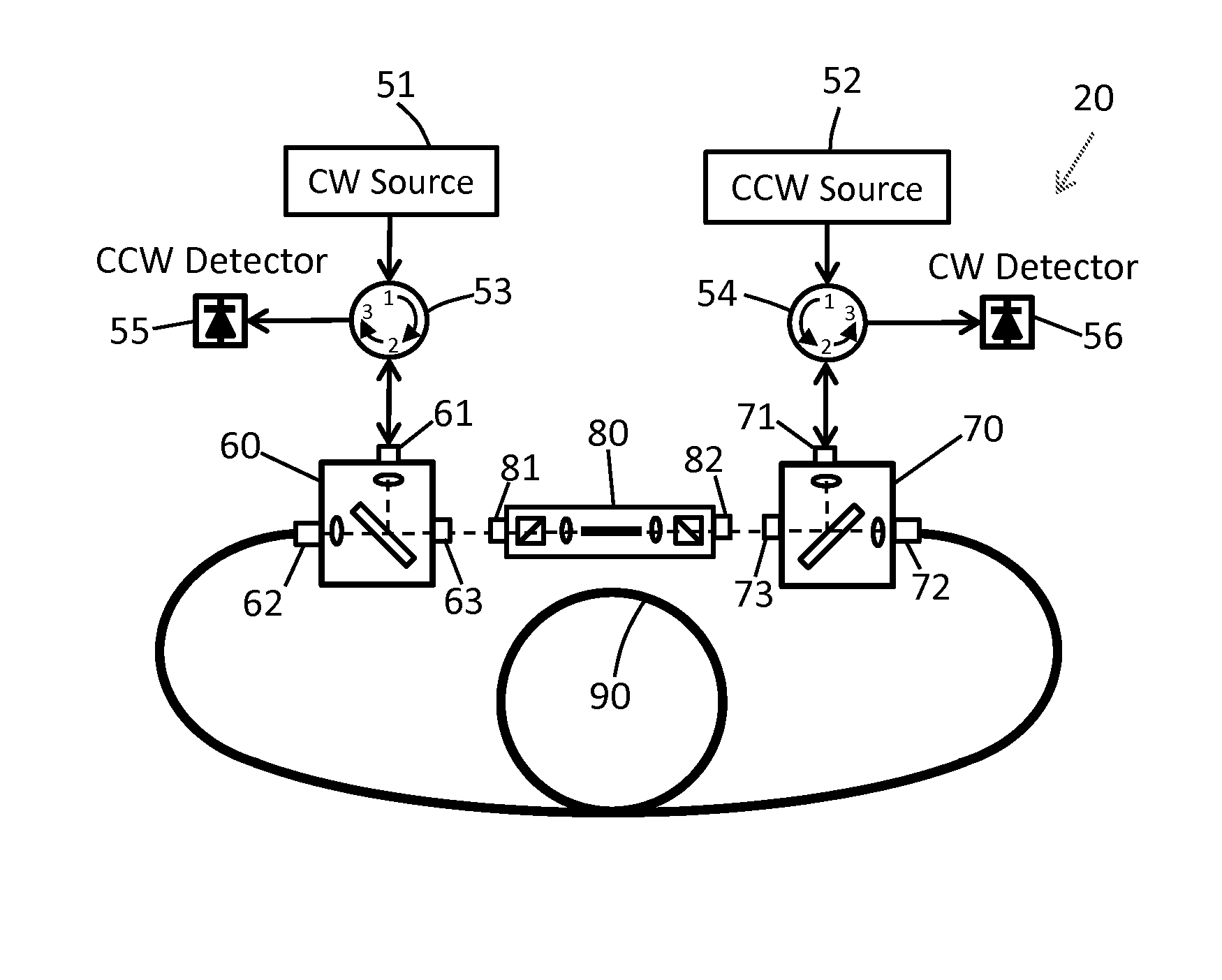
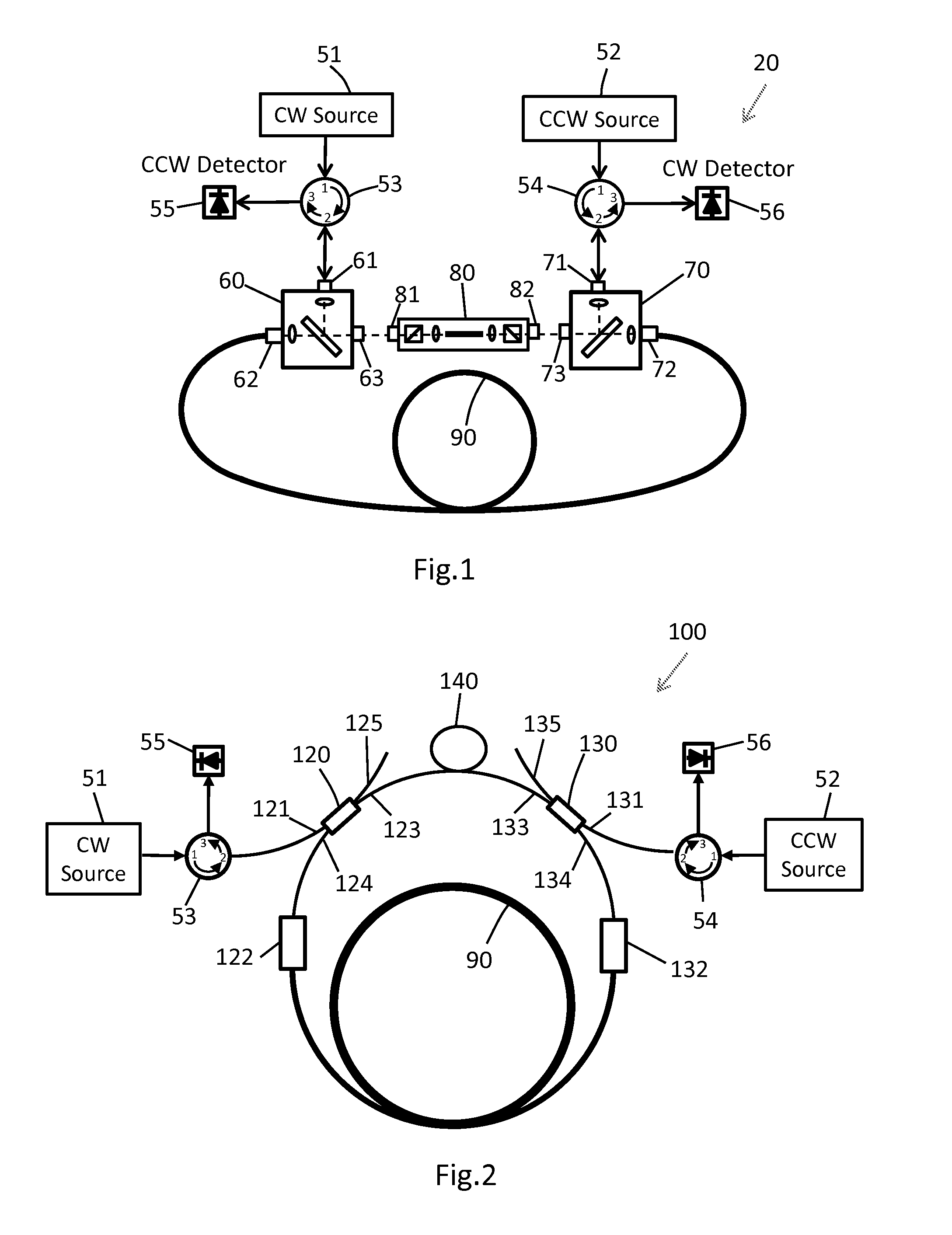
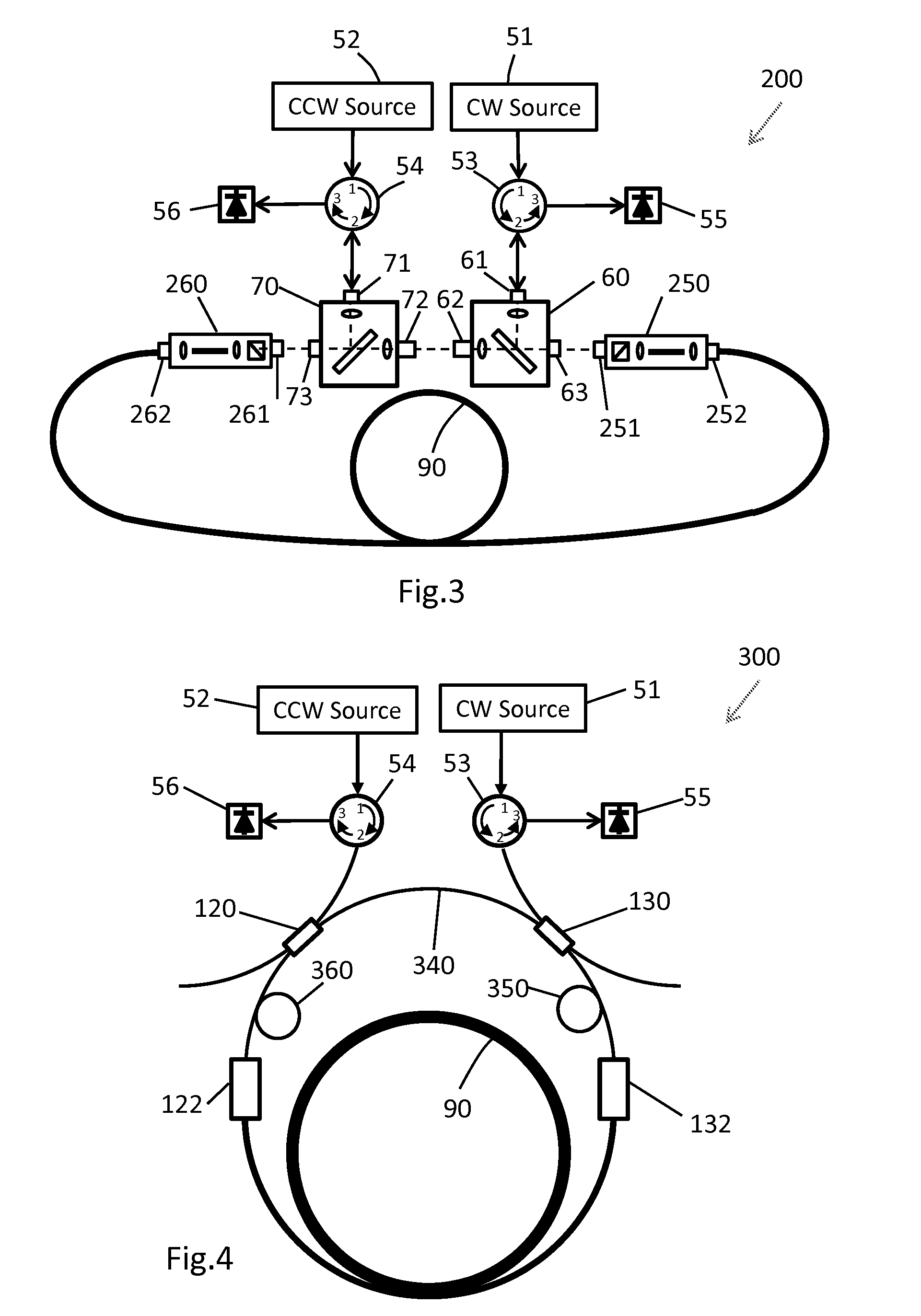
[0006]In one aspect of the invention, an RFOG includes a loop fiber having a first end and a second end, a first and a second in / out coupling element having at least three ports: A, B and C, a first and a second directional element having at least three ports: 1, 2, and 3, a first and a second light source, a first and a second detector, and a mode filter having a first and a second end. The (first or the second, which are substantially the same) in / out coupling element couples substantial amount of light from port A to port B and from port B to port A. A fraction of light is coupled from C to B and from B to C but prevents light from being coupled from port A to port C and from port C to port A. The (first or the second, which are substantially the same) directional element couples substantial amount of light from port 1 to port 2, from port 2 to port 3, but prevents light from being coupled from port 1 to port 3.
[0008]In all the embodiments, the light reaching the photodetector is filtered by at least one mode filter in the resonator. This significantly reduces / removes the impact of unwanted modes from interfering with the fundamental mode which is critical for accurate measurement of the resonance frequencies, and thus rotation rate.

Problems solved by technology

During the research of hollow core fiber gyroscopes, it was found that the current commercially available low loss hollow core fiber may weakly support high order spatial modes, sometimes by design, and sometimes due to imperfections in either design or manufacturing process.
When the resonator output light is detected, light from the higher order mode may interfere with the fundamental mode, producing resonance asymmetry that varies with environmental changes.
Although this interference may be suppressed to some degree by the spatial averaging of two spatially-orthogonal modes, the suppression may be compromised by imperfect spatial averaging; e.g. when the detected light is traveling through a finite aperture or the detector has spatial inhomogeneities.
Although possibly weak in intensity, the high order modes can be a severe limiting factor of bias stability of a high performance RFOG.

Method used


Image

  • Resonator fiber optic gyroscope (RFOG) with reduced bias error from high order spatial modes
  • Resonator fiber optic gyroscope (RFOG) with reduced bias error from high order spatial modes
  • Resonator fiber optic gyroscope (RFOG) with reduced bias error from high order spatial modes

Examples


Embodiment Construction

[0025]The present invention is described below for use in a resonator fiber optic gyroscope (RFOG) having a ring cavity. It should be understood that the ring cavity can include discrete optical elements and / or waveguide optical elements. The term “spatial modes” generally includes modes of waveguides, modes of the discrete optical elements, and modes of the free space between optical elements. Although the present invention is focused on suppression of unwanted high order spatial modes of the resonator (ring cavity), it does not mean to ignore suppression of the unwanted polarization modes. If not mentioned explicitly, the “single spatial mode filter” or simply “mode filter” may include highly polarizing elements (in addition to spatial mode filtering elements) that substantially suppress one polarization mode and pass the other polarization mode. The polarizing elements in the mode filter can be polarizing waveguides, polarizing fibers, and polarizers.

[0026]An ideal RFOG should su...


PUM


Abstract

Multiple resonator fiber optic gyroscope (RFOG) configurations comprising one or more mode filters inside the resonator are adopted to effectively suppress unwanted high order spatial modes which can be a significant source of gyro bias errors. The resonator comprises at least a loop fiber, either two or more in / out coupling elements, and connectors that link elements into a circulating loop. Directional elements may be used to separate output light from input light in some of the embodiments. In all embodiments, mode filters are placed in the resonator to guarantee that the light reaching the photodetector is filtered by at least one mode filter in the resonator at least once. The mode filters may contain both spatial mode filters (such as single mode fibers or waveguides) and polarization mode filters (such as polarizing elements) so that both spatial and polarization mode filtering can be implemented simultaneously.

Description

BACKGROUND OF THE INVENTION[0001]A resonator fiber optic gyroscope (RFOG) is a rotation sensing device that comprises a fiber resonant ring cavity. When the gyro has nonzero rotation rate around an axis normal to the plane of the ring cavity (also called resonator), the effective round trip path lengths for lightwaves propagating in the two opposite directions are different. This so-called Sagnac effect causes the ring cavity to exhibit different resonance frequencies for the two opposite directions which are often referred to as clockwise (CW) and counter-clockwise (CCW) for convenience. The resonance frequency difference is proportional to the gyro rotation rate.[0002]To measure the resonance frequency difference of the ring cavity in CW and CCW directions, monochromatic lightwaves are coupled into the resonator in both directions and their frequencies are separately tuned / locked to the peaks (or dips, depends on how light is coupled out of the resonator) of the resonance characte...

Claims


Application Information

Patent Timeline
IPC IPC(8): G01C19/72
CPCG01C19/727
Inventor SANDERS, GLEN A.QIU, TIEQUNSTRANDJORD, LEE
Owner HONEYWELL INT INC
Learn More