
Pilot signal transmission method and radio communication system for enabling measurement of reception quality with high accuracy

a radio communication system and high-accuracy technology, applied in the field of pilot signal transmission methods, can solve the problems of large degraded sir measurement accuracy, noise addition, and the inability of second pilot signals to be used in sir measurement for transmission power control, so as to improve throughput, reduce block error rate, and increase sir measurement accuracy

Active Publication Date: 2012-01-17
NEC CORP
View PDF12 Cites 2 Cited by
  • Summary
  • Abstract
  • Description
  • Claims
  • Application Information

AI Technical Summary

Benefits of technology

[0018]It is an object of the present invention to provide a pilot signal transmission method, a radio communication system, a base station and a mobile station that can solve the above-described problems. More specifically, it is an object of the present invention to provide a pilot signal transmission method, a radio communication system, a base station, and a mobile station that, in a system that uses EUDCH to perform high-speed packet transmission, raise SIR measurement accuracy for transmission power control during high-speed transmission and thus decrease the block error rate and improve throughput.

Problems solved by technology

Nevertheless, in this solution, there are cases in which the second pilot signal cannot be used in SIR measurement for transmission power control.
In this case, when the second pilot signals are not being transmitted, noise is added to the SIR measurement, and the SIR measurement accuracy is therefore greatly degraded.
As described hereinabove, when the SIR measurement accuracy deteriorates, the transmission power control accuracy also deteriorates, and as a result, the target reception quality cannot be achieved and the channel estimation accuracy deteriorates.
The problems therefore result that block errors increase and throughput decreases.

Method used


Image

  • Pilot signal transmission method and radio communication system for enabling measurement of reception quality with high accuracy
  • Pilot signal transmission method and radio communication system for enabling measurement of reception quality with high accuracy
  • Pilot signal transmission method and radio communication system for enabling measurement of reception quality with high accuracy

Examples


first working example

[0042]Explanation next regards the first working example.

[0043]FIG. 5 shows the method of transmitting pilot signals in the first working example. For the sake of simplicity, only the pilot signals and TFCII signals are described as control signals. DPDCH and DPCCH are transmitted continuously. On the other hand, E-DPCCH and E-DPDCH are transmitted intermittently, and the second pilot signals that are contained in E-DPCCH are transmitted only when the transmission speed is at least a prescribed threshold value. In this case, the transmission speed threshold value is set at 1024 kbps. The transmission speed of the first (left side) data block in the figure is 384 kbps and thus lower than the transmission speed threshold value, and the second pilot signals are therefore not transmitted (“DTX” in the figure indicates “Discontinuous Tx,” and means that transmission is OFF). However, the transmission speed of the subsequent data blocks is 1024 kbps, and the second pilot signals are there...

second working example

[0083]Explanation next regards the details of the second working example of the present invention.

[0084]As shown in FIG. 9, the mobile station in the second working example transmits second pilot signals when E-DPDCH is transmitted at a transmission speed that is at least a prescribed transmission speed threshold value, as in the first working example.

[0085]However, in contrast with the first working example, the mobile station in the second working example, when transmitting second pilot signals, transmits second pilot signals during a prescribed pilot signal transmission time interval from the next TTI regardless of the transmission speed. The mobile station does not transmit second pilot signals during the transmission of the first data block in the figure (a data block of 384 kbps), but during the transmission of the second data block (a data block of 1024 kbps), the mobile station transmits second pilot signals, and in the next TTI, transmits second pilot signals but does not t...

third working example

[0095]Explanation next regards the third working example of the present invention.

[0096]As shown in FIG. 12, a mobile station also transmits second pilot signals according to a prescribed transmission speed threshold value in the third working example, similar to the first working example. However, in contrast to the case of the first working example, a mobile station in the third working example transmits second pilot signals when the transmission speed according to a maximum TFC that is designated in the base station (maximum transmission speed) is at least a prescribed transmission speed threshold value. In the figure, the third bar from the top shows the data block that is actually being transmitted in E-DPDCH and its transmission speed. The second bar from the top shows the maximum transmission speed that is permitted for use in E-DPDCH. In this case, because the transmission speed threshold value is set to 768 kbps, second pilot signals are not transmitted in the first TTI in ...


PUM


Abstract

In a pilot signal transmission method for raising the SIR measurement accuracy for transmission power control during high-speed transmission and thus reducing the block error rate and improving the throughput, a first SIR value measured by first pilot signals and second SIR value measured by second pilot signals are first compared, and the presence or absence of second pilot signals then determined in slot units based on the comparison results. When the second pilot signals exist, the second pilot signals are used in addition to the first pilot signals in the SIR measurement for high-speed closed-loop transmission power control. When the second pilot signals do not exist, only the first pilot signals are used in the SIR measurement for high-speed closed-loop transmission power control.

Description

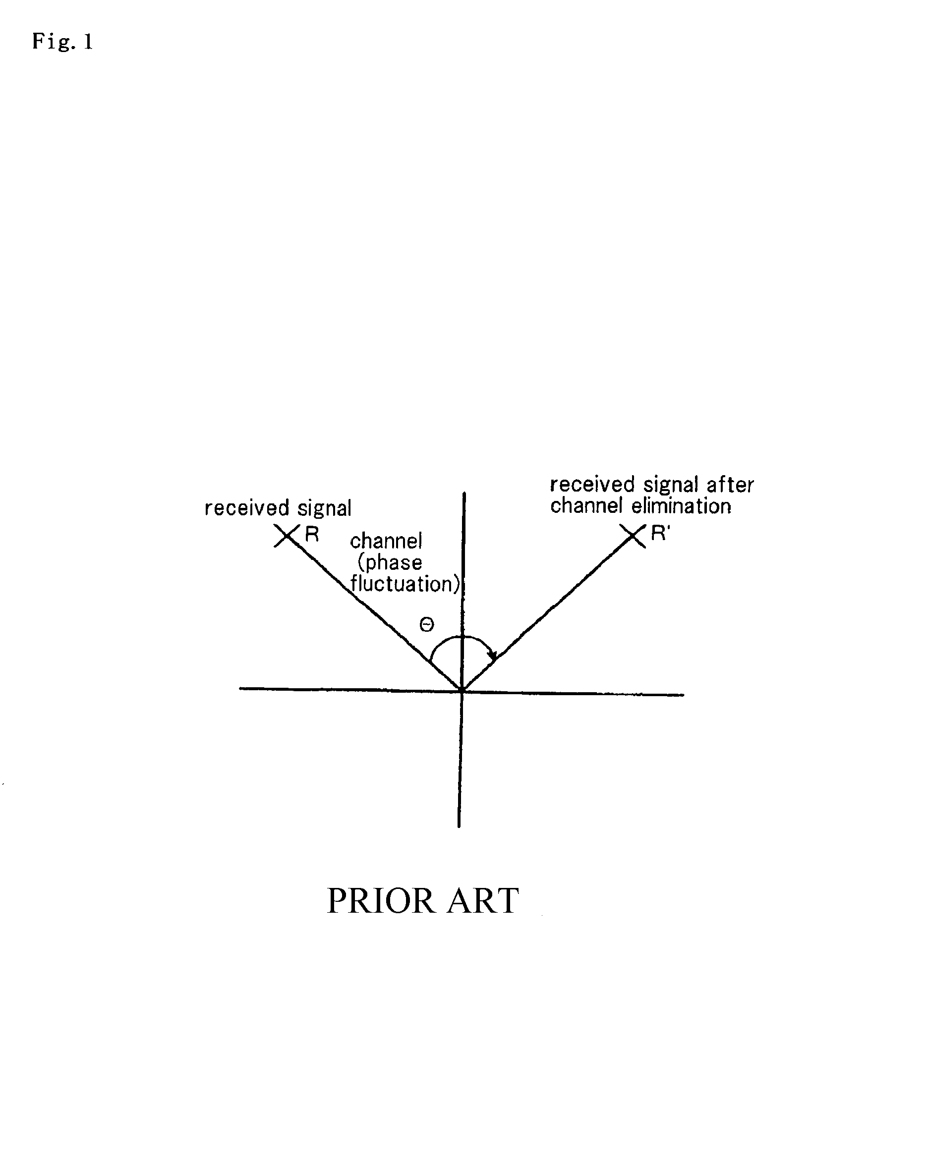
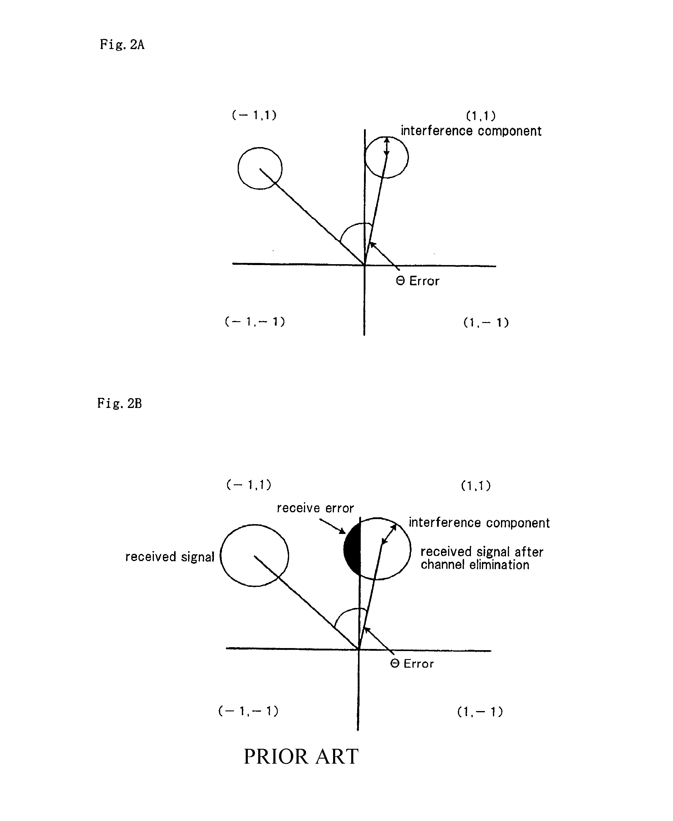
TECHNICAL FIELD[0001]The present invention relates to a pilot signal transmission method in a radio communication system that performs high-speed packet transmission.BACKGROUND ART[0002]In a radio communication system, Rayleigh fading occurs with the movement of mobile stations. This Rayleigh fading gives rise to amplitude fluctuation and phase fluctuation in the communication channels. As a result, in a radio communication system such as WCDMA, the transmitting side transmits an already known signal string (pilot signal) on the receiving side. The receiving side estimates the phase fluctuation and amplitude fluctuation of the propagation path based on the differences between the received points of the pilot signal and the already known transmission points (channel estimation). Based on this channel estimation, the receiving side then corrects the fluctuation of the phase and amplitude of an information signal that contains a control signal or data signal (channel elimination).[0003...

Claims


Application Information

Patent Timeline
Patent Type & Authority Patents(United States)
IPC IPC(8): H04B14/06H04B1/707H04B1/7097
CPCH04W52/24H04W52/146H04W52/246H04B17/309H04W52/286H04W52/42H04W52/248
Inventor KURODA, NAHOKOLEE, JINSOCKHAMABE, KOJIROUSHIROKAWA, AKIHISA
Owner NEC CORP
Learn More