Method for manufacturing boundary acoustic wave device

a technology of boundary acoustic wave and manufacturing method, which is applied in the direction of superimposed coating process, magnetic bodies, instruments, etc., can solve the problems of inability to achieve a sufficiently large electromechanical coefficient, increase electrical resistance, and deterioration of the obtained boundary acoustic wave device, so as to achieve effective and reliably prevent the effect of reducing the thickness of the id

Active Publication Date: 2012-01-24
MURATA MFG CO LTD
View PDF14 Cites 2 Cited by
  • Summary
  • Abstract
  • Description
  • Claims
  • Application Information

AI Technical Summary

Benefits of technology

[0019]Preferred embodiments of the present invention provide a method for manufacturing a boundary acoustic wave device that solves the problems of existing technologies and includes a step of forming a dielectric film by deposition. In the method, the creation of elastic discontinuous portions in a dielectric film is effectively and reliably prevented without a significant decrease in the thickness of an IDT.

Problems solved by technology

As a result, the characteristics of the obtained boundary acoustic wave device may deteriorate.
However, if the thickness of the IDT is excessively decreased, an electrical resistance is increased or a sufficiently large electromechanical coefficient cannot be achieved.

Method used


Image

  • Method for manufacturing boundary acoustic wave device
  • Method for manufacturing boundary acoustic wave device
  • Method for manufacturing boundary acoustic wave device

Examples


Embodiment Construction

[0043]Preferred embodiments of the present invention will now be described with reference to drawings to clarify the present invention.

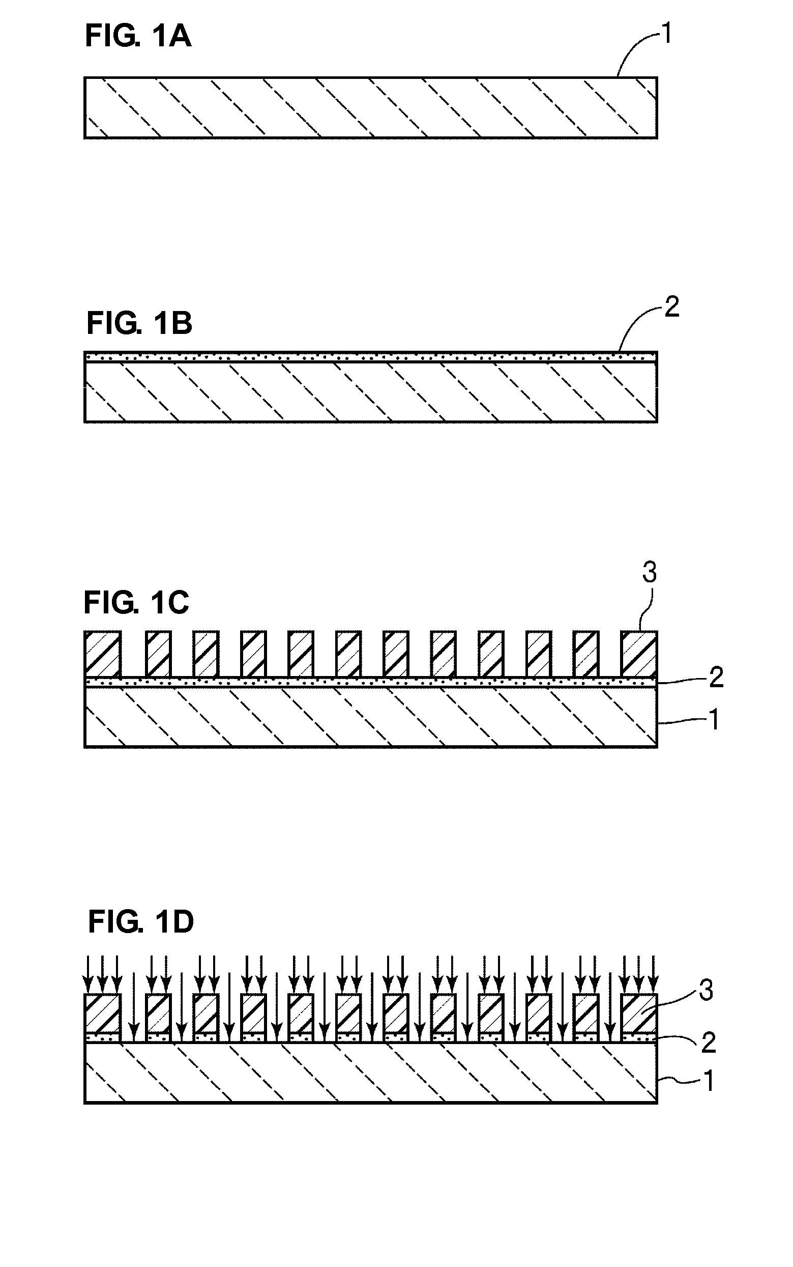
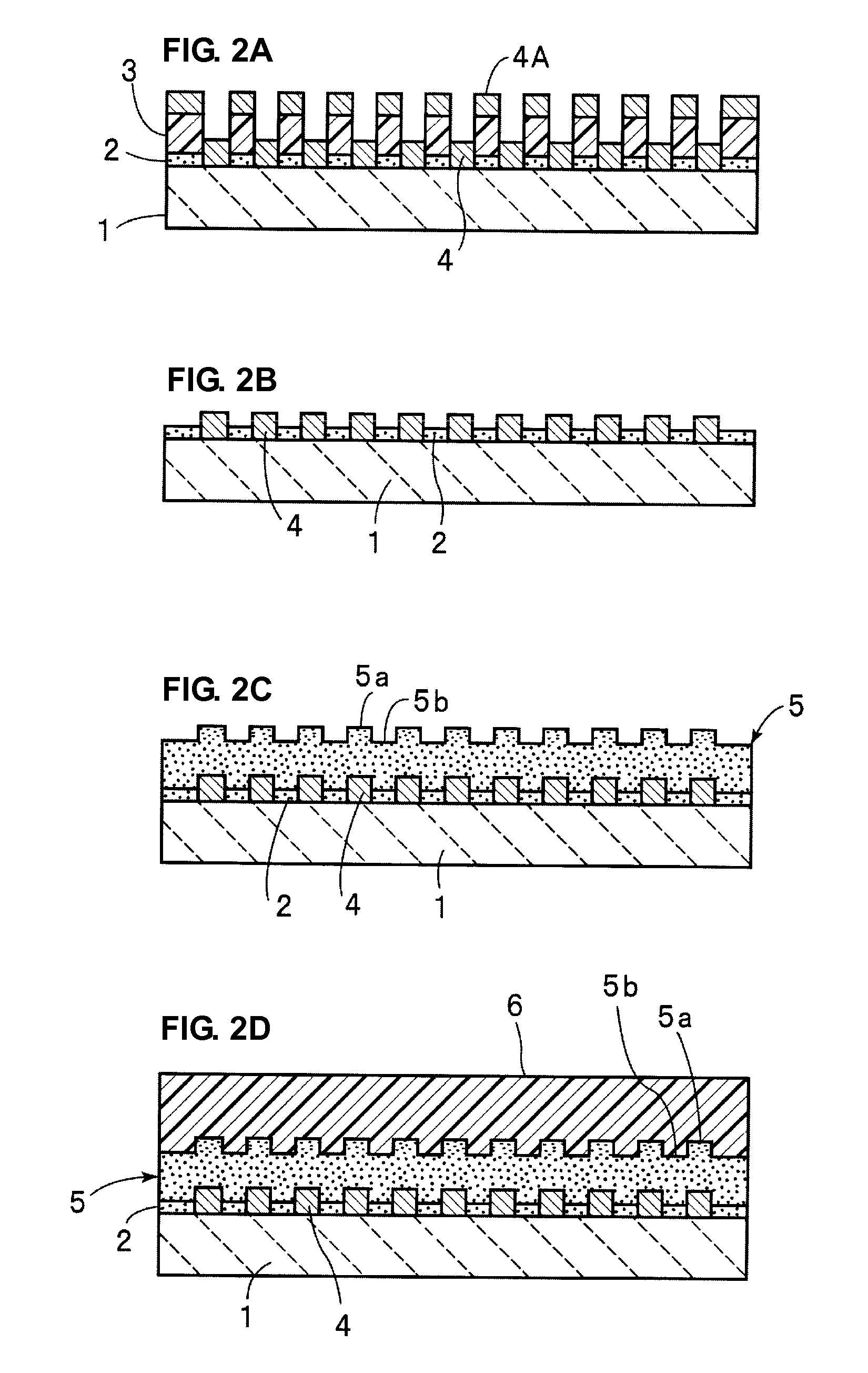
[0044]A manufacturing method according to a first preferred embodiment of the present invention will be described with reference to FIGS. 1A to 1D, 2A to 2D, 3A, and 3B.

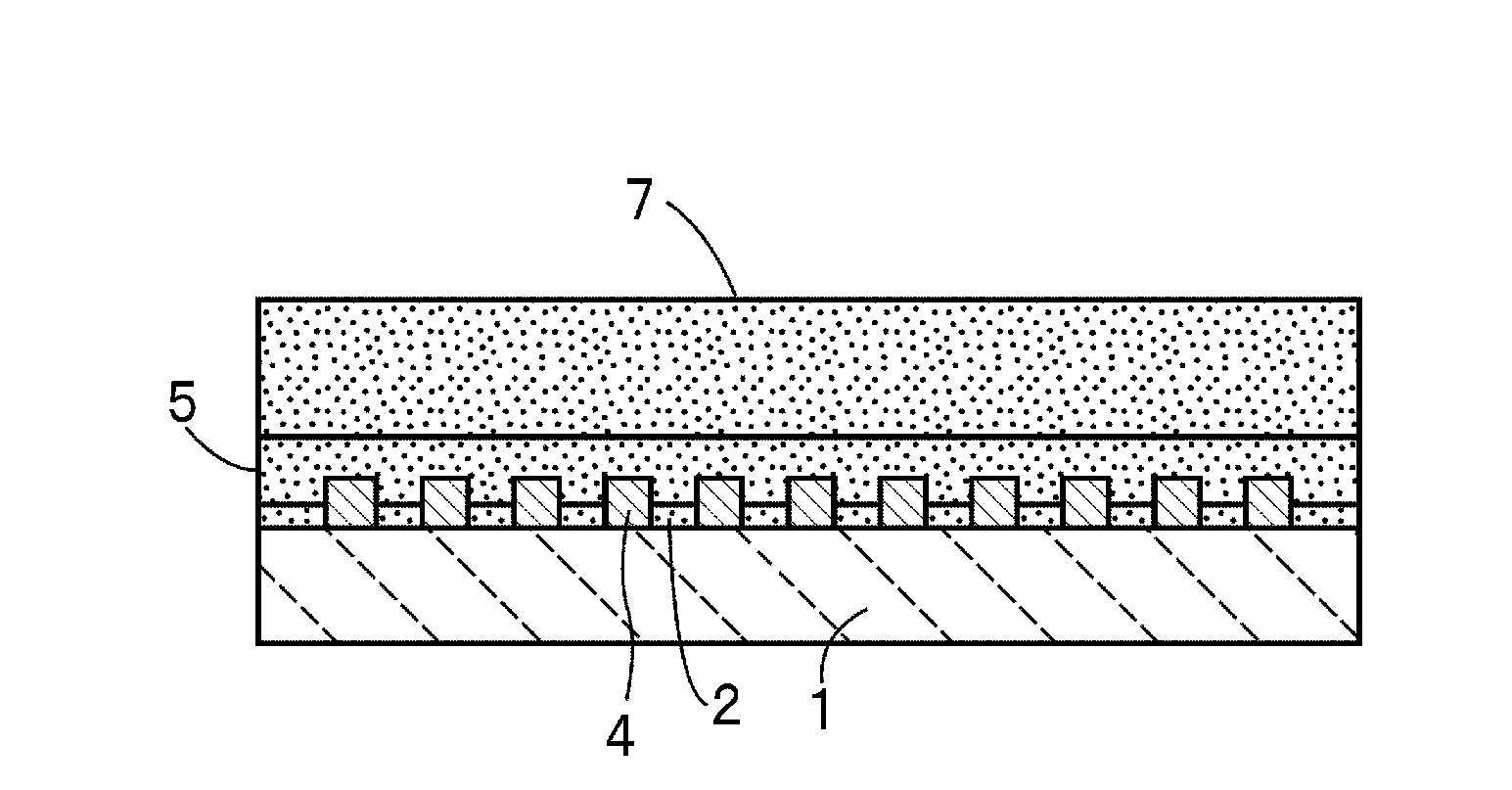
[0045]In the method for manufacturing a boundary acoustic wave device according to this preferred embodiment, a piezoelectric substrate 1 is prepared first as shown in FIG. 1A. In this preferred embodiment, the piezoelectric substrate 1 preferably is composed of 15° Y-cut X-propagation LiNbO3, for example. However, other materials may be used to form the substrate 1.

[0046]As shown in FIG. 1B, a thickness-adjusting dielectric film 2 is then formed on the piezoelectric substrate 1 by sputtering, for example. The thickness-adjusting dielectric film 2 is made of SiO2. The sputtering is conducted using Ar gas and O2 gas at a film formation temperature of approximately 200° C. at a gas pres...


PUM

PropertyMeasurementUnit
thicknessaaaaaaaaaa
thicknessaaaaaaaaaa
wavelengthaaaaaaaaaa

Abstract

A method for manufacturing a boundary acoustic wave device prevents formation of discontinuous portions in a dielectric film without a significant decrease in the thickness of an IDT when the dielectric film is formed by deposition and without deterioration of electrical characteristics. The method includes the steps of forming an IDT on a piezoelectric substrate, forming a lower dielectric film so as to cover the IDT, conducting a planarizing step so as to smooth the rough surface of the lower dielectric film, and forming an upper dielectric film so as to cover the lower dielectric film of which the rough surface is smoothed.

Description

BACKGROUND OF THE INVENTION[0001]1. Field of the Invention[0002]The present invention relates to a method for manufacturing a boundary acoustic wave device, for use in a resonator or a band-pass filter, for example. More specifically, the present invention relates to a method for manufacturing a boundary acoustic wave device having a structure in which a film unevenness of a dielectric substance is improved.[0003]2. Description of the Related Art[0004]Surface acoustic wave devices are widely used for band-pass filters of cellular phones or the like. On the other hand, instead of such surface acoustic wave devices, boundary acoustic wave devices have been studied for simplifying and downsizing of a package structure.[0005]WO2004 / 070946 discloses one example of a method for manufacturing a boundary acoustic wave device. In the manufacturing method described in WO2004 / 070946, first, an electrode including an IDT is formed on a piezoelectric substrate composed of LiNbO3 or the like by p...

Claims


Application Information

Patent Timeline
Patent Type & Authority Patents(United States)
IPC IPC(8): H04R31/00H03H3/08H03H9/145
CPCH03H3/08H03H9/0222Y10T29/4908Y10T29/49007Y10T29/49005Y10T29/42
Inventor KANDO, HAJIMENODAKE, NAOHIROSAEKI, MASAHIKOFUYUTSUME, TOSHIYUKI
Owner MURATA MFG CO LTD
Why Eureka
Try Eureka