Measuring device and measuring method for measuring the envelope power and the mean-power value

a measurement device and high-frequency signal technology, applied in measurement devices, electric power measurement, instruments, etc., can solve the problems of extremely complex design of the measuring device and relatively poor signal level at the lower end of the dynamic range, so as to reduce the noise of 1/f and minimize the influence of thermal drift

Inactive Publication Date: 2012-01-24
ROHDE & SCHWARZ GMBH & CO KG
View PDF28 Cites 6 Cited by
  • Summary
  • Abstract
  • Description
  • Claims
  • Application Information

AI Technical Summary

Benefits of technology

[0007]The invention is based upon the object of providing a measuring device and a measuring method for measuring the envelope power and the mean-power value of a high-frequency signal, which allow / s good measurement accuracy in spite of the use of only a single measurement branch.
[0008]According to the invention, it is proposed to supply a dither signal upstream of the analog / digital conversion, wherein a different dither signal is used for the measurement of the envelope power than for the measurement of the mean-power value. This allows an optimum adaptation of the dither signal to the measurement task.
[0010]If the mean-power value is to be measured instead, it is advantageous to use a different dither signal, namely a type of dither signal, which changes constantly from one sampled value to the next sampled value and accordingly allows an optimal suppression of the discretization error through continuous variation of the discretization thresholds of the analog / digital converter relative to the measured signal. In order to detect the mean-power value, it is not necessary for the measured signal to be changed during the measurement recording, because the variation of the individual power values caused by the dither disappears in the statistical average as a result of the averaging of individual measured power values implemented in calculating the mean power value.
[0011]The first dither signal used for the measurement of the envelope power is preferably a piecewise-constant signal, which is generated with a large amplitude variation with identical relative frequency of the individual values. For example, a counter, which generates continuously-incremented digital words, is suitable for generating a signal of this kind. In interpreting the counter result, if the value of the bits is reversed, that is to say, the least-significant bit (LSB) is exchanged with the most-significant bit (MSB) in an offset binary presentation, a digital-value sequence is obtained, which continuously changes its sign and its amplitude. Through digital / analog conversion, an analog signal can then be generated, which can be added to the measured signal before the analog / digital conversion. The elimination in the equivalent digital signal after the analog / digital conversion can then be implemented in a very simple manner by once again subtracting, or respectively by adding with an inverted sign, the digital value of the dither signal from / to the digital value.
[0013]To reduce the 1 / f noise and to minimize the influence of thermal drift in the DC amplifier, it is advantageous to arrange a chopper in front of the DC amplifier, which periodically chops the analog detector signal with a chopper signal. The signal inversion caused by chopping can subsequently be removed from the digital signal by a synchronous demodulator.

Problems solved by technology

The disadvantage of the measuring device known from DE 199 55 342 A1 is the use of parallel measurement branches, as a result of which the measuring device suffers from an extremely complex design.
In practice, this causes problems, especially with regard to video bandwidths to be realized within the order of magnitude of 30 MHz.
This leads to a relatively poor signal level at the lower end of the dynamic range.

Method used


Image

  • Measuring device and measuring method for measuring the envelope power and the mean-power value
  • Measuring device and measuring method for measuring the envelope power and the mean-power value
  • Measuring device and measuring method for measuring the envelope power and the mean-power value

Examples


Embodiment Construction

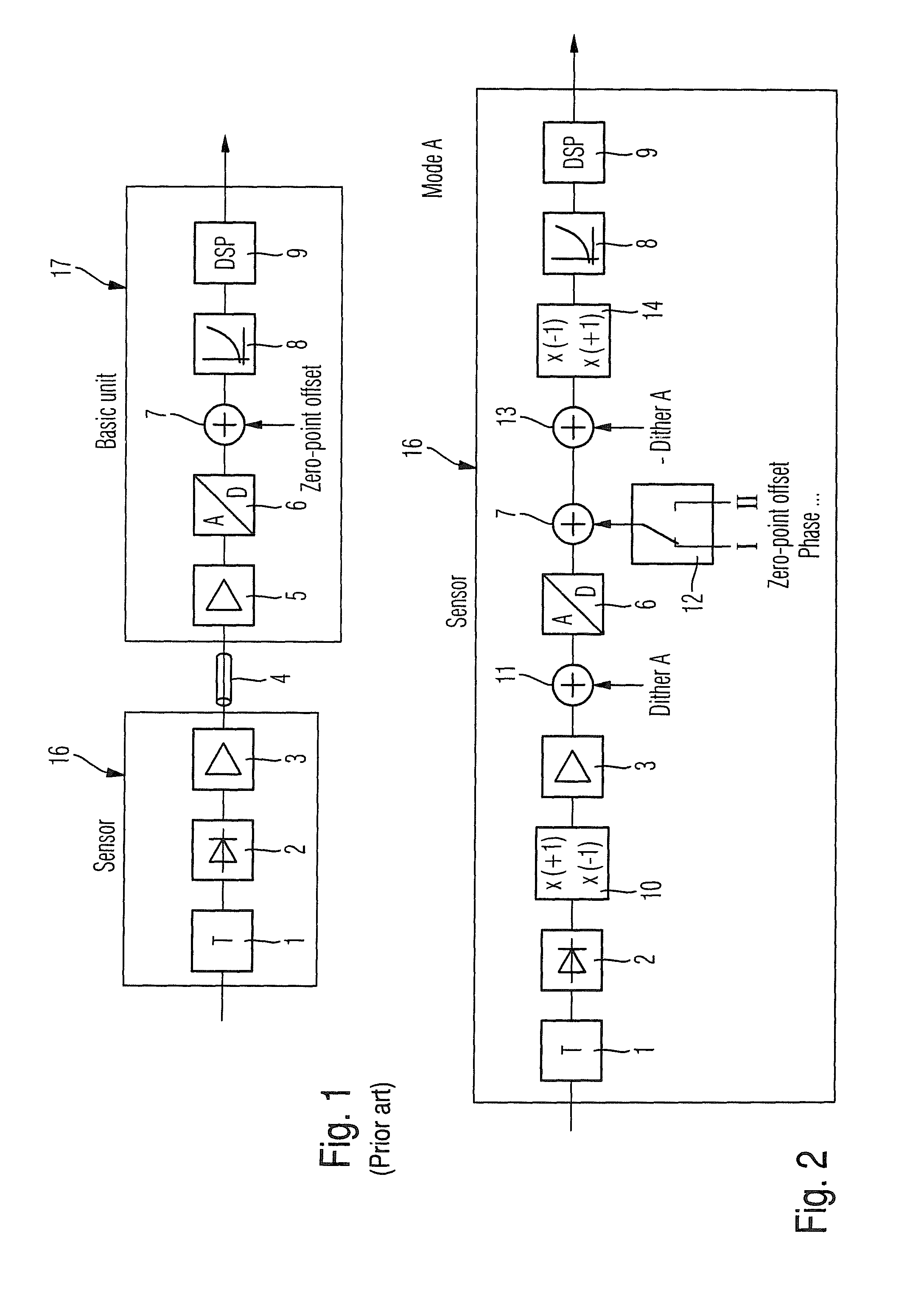
[0023]FIG. 1 shows a hitherto usual configuration of a measuring device for measuring the envelope-power and the average-power value. An attenuation element 1, an envelope detector 2, which can be designed as a diode detector, and a pre-amplifier or respectively line driver 3 are arranged in a sensor 16. The sensor 16 is connected via a connecting cable 4 to the basic unit 17. The main amplifier 5, an analog / digital converter 6, a summation stage 7 for subtraction of the zero-point offset, a device 8 for curve correction and a digital signal processor with further evaluation functions, for example, for displaying the envelope curves, for calculation of the average-power value and so on, are disposed in the basic unit 17. The device for curve correction 8 and the digital signal processor 9 together form an evaluation device 8, 9.

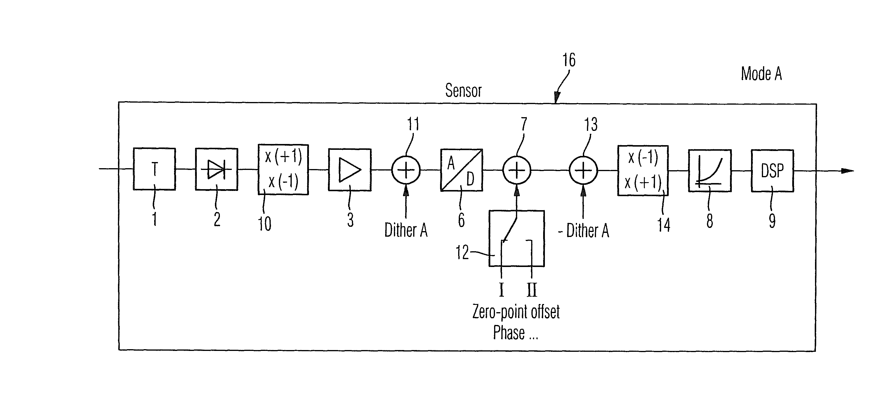
[0024]FIG. 2 shows an exemplary embodiment of the measuring device according to the invention in a first operating mode A, which is used for measuring the en...


PUM


Abstract

A measuring device for measuring the envelope power and the mean-power value of a high-frequency signal. The measuring device includes a detector for detecting the high-frequency signal and for generating an analog detector signal, an analog / digital converter for generating a digital signal and an evaluation device for evaluating the digital signal. A dither supply device for the supply of a dither signal is disposed between the detector and the analog / digital converter, and a dither elimination device for eliminating the dither signal is disposed between the analog / digital converter and the evaluation device. The dither supply device supplies a different dither signal for the measurement of the envelope power than for the measurement of the mean-power value.

Description

CROSS-REFERENCE TO RELATED APPLICATION[0001]The present application claims priority to PCT Application No. PCT / EP2007 / 003701, filed on Apr. 26, 2007, German Patent Application No. 10 2006 024 698.5, filed on May 26, 2006, and German Patent Application No. 10 2006 038 031.2, filed on Aug. 14, 2006, the entire contents of which are herein incorporated by reference.BACKGROUND OF THE INVENTION[0002]1. Field of the Invention[0003]The invention relates to a measuring device for measuring the envelope power and the mean-power value of a high-frequency signal.[0004]2. Discussion of the Background[0005]A measuring device is known from DE 199 55 342 A1. With the measuring device disclosed in this specification, it is possible to measure both the envelope power and also the mean-power or RMS (root mean square) value. To cover the maximum possible dynamic range, the measurement range is divided into several subdivisions, which are allocated respectively to several measurement branches arranged ...

Claims


Application Information

Patent Timeline
Patent Type & Authority Patents(United States)
IPC IPC(8): G01R23/00
CPCG01R19/02G01R19/04G01R19/2506G01R21/01
Inventor REICHEL, THOMASBRATFISCH, TORALFKATZER, MICHAEL
Owner ROHDE & SCHWARZ GMBH & CO KG
Why Eureka
Try Eureka