Method, coupler and apparatus for measuring radiated power

a technology of radiation power and coupler, which is applied in the direction of spectral/fourier analysis, instruments, transmission monitoring, etc., can solve the problems of complicated measuring apparatus, short measurement time, and device without test terminal, and achieve the effect of short measurement time, small size and high accuracy

Active Publication Date: 2012-01-24
ANRITSU CORP
View PDF12 Cites 11 Cited by
  • Summary
  • Abstract
  • Description
  • Claims
  • Application Information

AI Technical Summary

Benefits of technology

[0035]The present invention solves these problems and provides a method for measuring a radiation power, a coupler for measuring a radiation power, and an apparatus for measuring a radiation power, wherein total radiation power (TRP) can be measured with a simple configuration, in a short time, and with high sensitivity.
[0110]Moreover, the method for measuring a radiation power and the apparatus for measuring a radiation power in accordance with an aspect of the present invention handle total radiation power and thus can be applied to antennas having various directivities without limiting the directivity of an antenna of a device under test 1 to be used.

Problems solved by technology

Many of these devices do not have test terminals as do conventional radio devices, due to dimensional restrictions and economical reasons.
Of them, for EIRP, a measuring apparatus is complicated and measurement requires a long time and thus TRP is handled more and more.

Method used


Image

  • Method, coupler and apparatus for measuring radiated power
  • Method, coupler and apparatus for measuring radiated power
  • Method, coupler and apparatus for measuring radiated power

Examples


first embodiment

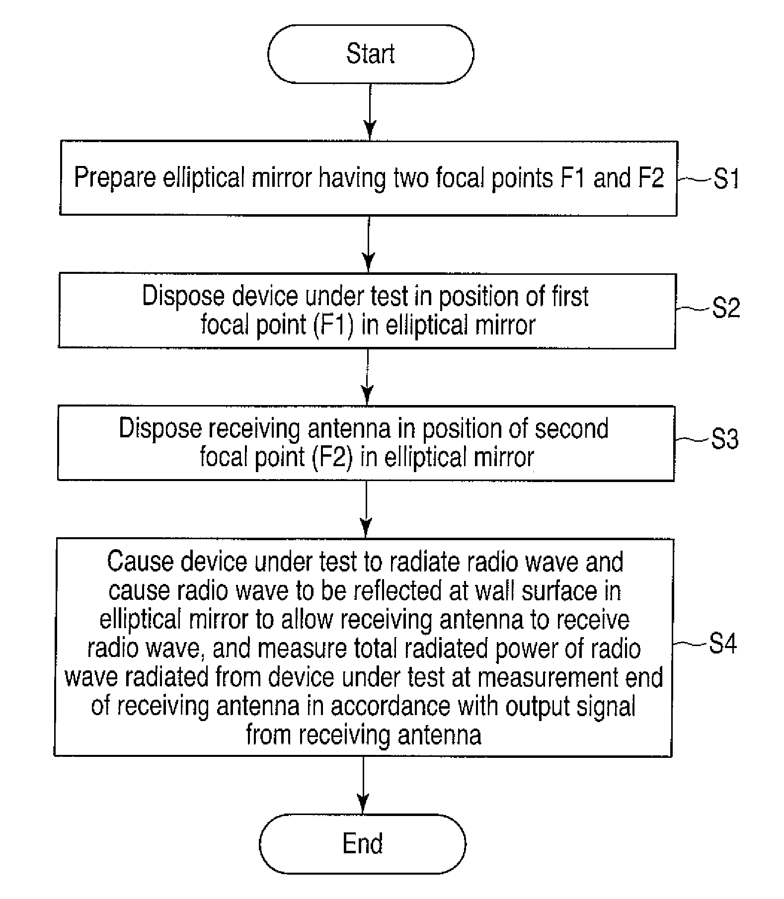
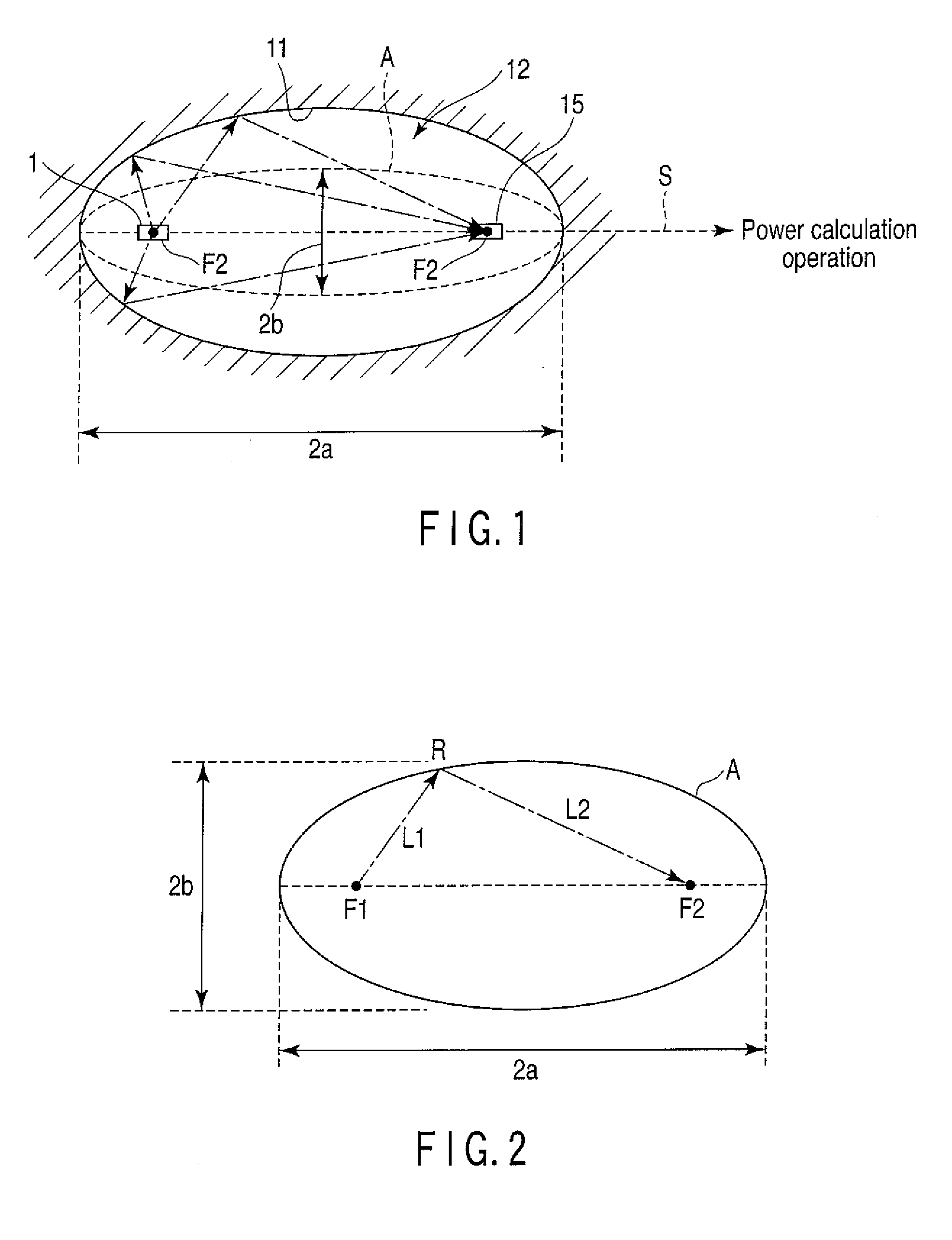
[0146]More specifically, in a method for measuring a radiation power according to a first embodiment of the present invention, as illustrated in FIG. 16, first, an elliptical mirror 10 is prepared that has, as described above, a closed space 12 which has an elliptical spherical shape obtained by rotating an ellipse by a predetermined angle about an axis line passing through two focal points F1 and F2 thereof and which is enclosed by a metal wall surface 11 (step S1).

[0147]Then, in the closed space 12 of the elliptical mirror 10 having the two focal points F1 and F2 which is prepared at step S1, a device under test 1 which can radiate a radio wave, such as a small wireless communication terminal, is disposed in the position of one of the two focal points F1 and F2, e.g., the focal point F1, on a rotation axis (long axis or short axis) line such that the center of radiation of a radio wave therefrom substantially coincides with the focal point F1 (step S2).

[0148]Subsequently, in the c...

second embodiment

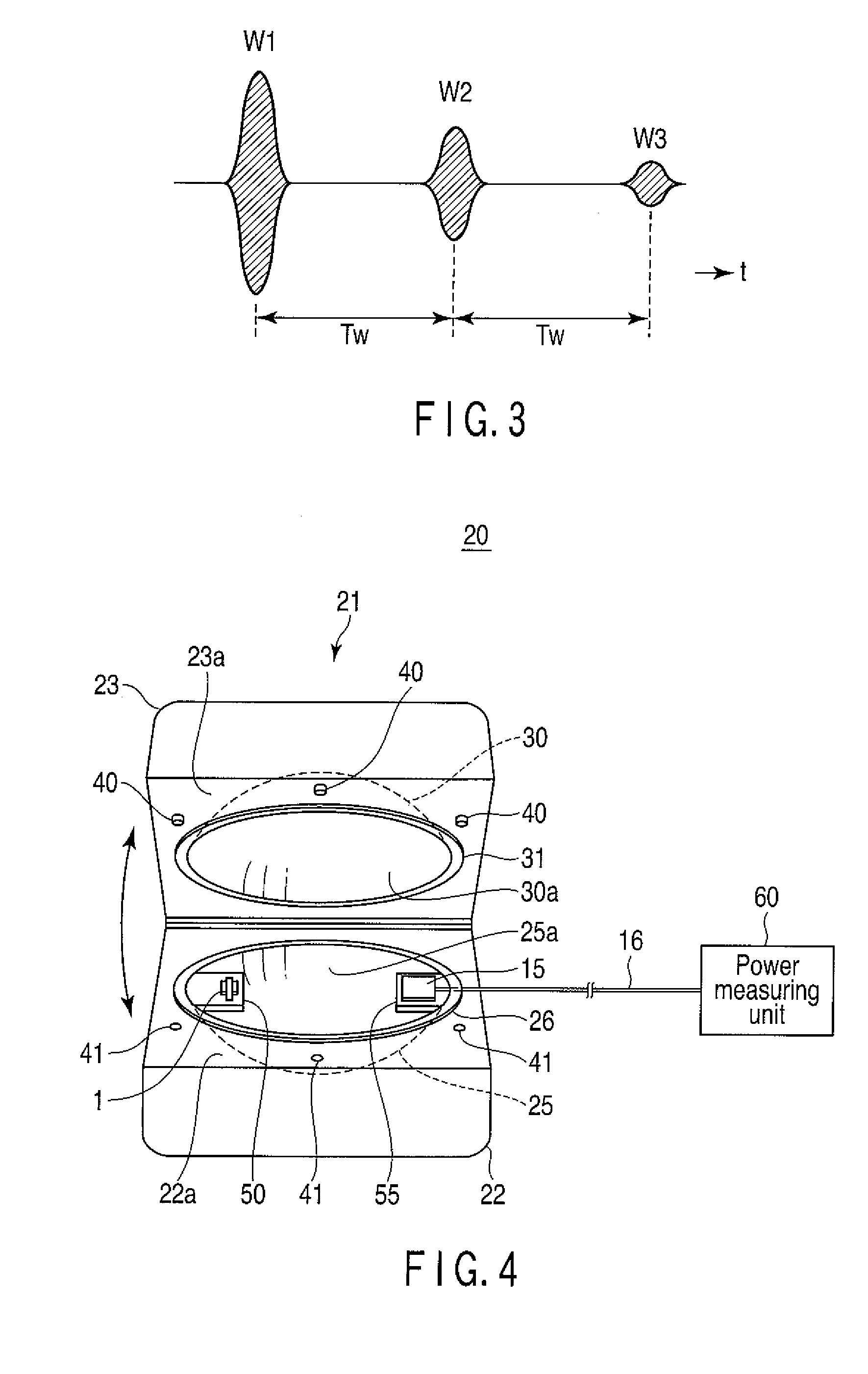
[0156]When a radio wave that is radiated from the device under test 1 and reflected once at the wall surface 11 and reaches the receiving antenna 15 at the focal point F2 is a primary wave, inside the closed space 11 of the elliptical mirror 10 such as that described above, there are multiple reflections where a secondary wave being a radio wave which is scattered by the receiving antenna 15 having received the primary wave and is reflected again at the wall surface 11 and returns to the focal point F1 and is further reflected at the wall surface 11 and inputted to the receiving antenna 15 at the focal point F2, or higher-order radio waves are inputted to the receiving antenna 15.

[0157]When there are such multiple reflections, a large standing wave is set up inside the closed space 11 of the elliptical mirror 10 and an electromagnetic field has a complicated distribution and thus it becomes difficult to accurately measure total radiation power of a radio wave radiated from the devic...

third embodiment

[0212]A method for measuring a radiation power according to a third embodiment of the present invention is configured such that step S4 in the aforementioned first embodiment where the total radiation power is measured at the measurement end of the receiving antenna 15 includes steps S5a, S6a, and S7a such as those illustrated in FIG. 22.

[0213]Specifically, when the total radiation power is measured at the measurement end of the receiving antenna 15, as illustrated in FIG. 22, first, for each of a plurality of measurement frequencies which are predetermined in a predetermined frequency range, with a continuous wave which has the predetermined measurement frequency being radiated from the device under test 1, received power PL of the receiving antenna 15 is sequentially measured through the measurement end of the receiving antenna 15 (step S5a).

[0214]Then, with the radio wave radiation from the device under test 1 being stopped, for each of the plurality of measurement frequencies wh...


PUM


Abstract

In a method for measuring a radiation power, an elliptical mirror is prepared so as to have a elliptical spherical space enclosed by a metal wall surface, the space having a rotating axis passing through two focal points. A device under test is placed in a position of one of the two focal points such that a center of radiation of a radio wave substantially coincides with the focal point, and a receiving antenna is placed in an position of an other one of the two focal points. The device under test is caused to radiate a radio wave and the radiated radio wave is reflected at the wall surface to allow the receiving antenna to receive the radio wave. Then, total radiation power of the radio wave is measured at a measurement end of the receiving antenna in accordance with an output signal from the receiving antenna.

Description

CROSS REFERENCE TO RELATED APPLICATIONS[0001]This is a Continuation Application of PCT Application No. PCT / JP2008 / 067315, filed Sep. 25, 2008, which was published under PCT Article 21(2) in Japanese.[0002]This application is based upon and claims the benefit of priority from prior Japanese Patent Application No. 2007-253643, filed Sep. 28, 2007, the entire contents of which are incorporated herein by reference.BACKGROUND OF THE INVENTION[0003]1. Field of the Invention[0004]The present invention relates to a method for measuring a radiation power, a coupler for measuring a radiation power, and an apparatus for measuring a radiation power. More particularly, the present invention relates to a method for measuring a radiation power, a coupler for measuring a radiation power, and an apparatus for measuring a radiation power, wherein a technology for measuring a radiation power of, for example, a small wireless communication terminal serving as a device under test, with a simple configur...

Claims


Application Information

Patent Timeline
Patent Type & Authority Patents(United States)
IPC IPC(8): G01R29/08
CPCG01R29/0821H04B17/102H01Q19/13
Inventor TESHIROGI, TASUKUHINOTANI, AYAKAWAMURA, TAKASHISAKUMA, TORU
Owner ANRITSU CORP
Why Eureka
Try Eureka