Positioning device to position one or more plates of electronic circuits, in a metal deposition unit

a technology of electronic circuits and metal deposition units, which is applied in the direction of metal working apparatus, printed circuit manufacture, manufacturing tools, etc., can solve the problems of unavoidable productivity reduction, increased production costs, and long maintenance steps, and reduce the thermal difference between the plate and the metallic paste, hot or cold, deposited on the plate, and reduce the risk of both imprecision. , the effect of reducing the risk of imprecision

Inactive Publication Date: 2012-01-31
APPLIED MATERIALS ITALIA SRL
View PDF8 Cites 0 Cited by
  • Summary
  • Abstract
  • Description
  • Claims
  • Application Information

AI Technical Summary

Benefits of technology

[0023]The selective dismantling of the device therefore allows to speed up and simplify the operations to replace the belt, limiting possible interruptions in production to a minimum, increasing productivity and reducing the overall management costs of the transport member.
[0027]According to another variant, the removable frame also comprises lighting means disposed below the transpirant belt so as to determine a retro-illumination effect, and to facilitate the operations to control and correct the position of the plate on the transpirant belt.
[0031]In this way, the thermal difference between the plate and the metallic paste, hot or cold, deposited on the plate, is considerably reduced. This considerably limits the risk both of imprecisions and of smudges in the deposition, and the formation of cracks or breaks during drying.

Problems solved by technology

This entails a consequent increase both in production costs, and in the operating time of the plant, with an unavoidable reduction in productivity.
This solution, even if it allows to guide the deposition of the plates on the turret, entails long maintenance steps and therefore inactivity of the plant, due to the need to control, each time, the efficiency of the paper strip after the treatment, and also to perform a periodical substitution of the paper strip, once this has been completely wound onto one of the rollers.
Furthermore, such maintenance steps are rather complex and require the intervention of particularly qualified personnel, or the use of sophisticated or particularly expensive equipment.
In both known solutions, errors can occur, or smudges, in the deposition of the metallic tracks, mainly due to the relatively high differences in temperature between the printed paste and the surface of the plate.
In the state of the art, due to the high thermal gradient of the paste, difficulties or imperfections have also been found in the drying of the printed paste.
This entails both incorrect prints and cracks or breaks that can interrupt or modify the correct conductivity of the printed tracks.

Method used


Image

  • Positioning device to position one or more plates of electronic circuits, in a metal deposition unit
  • Positioning device to position one or more plates of electronic circuits, in a metal deposition unit
  • Positioning device to position one or more plates of electronic circuits, in a metal deposition unit

Examples


Embodiment Construction

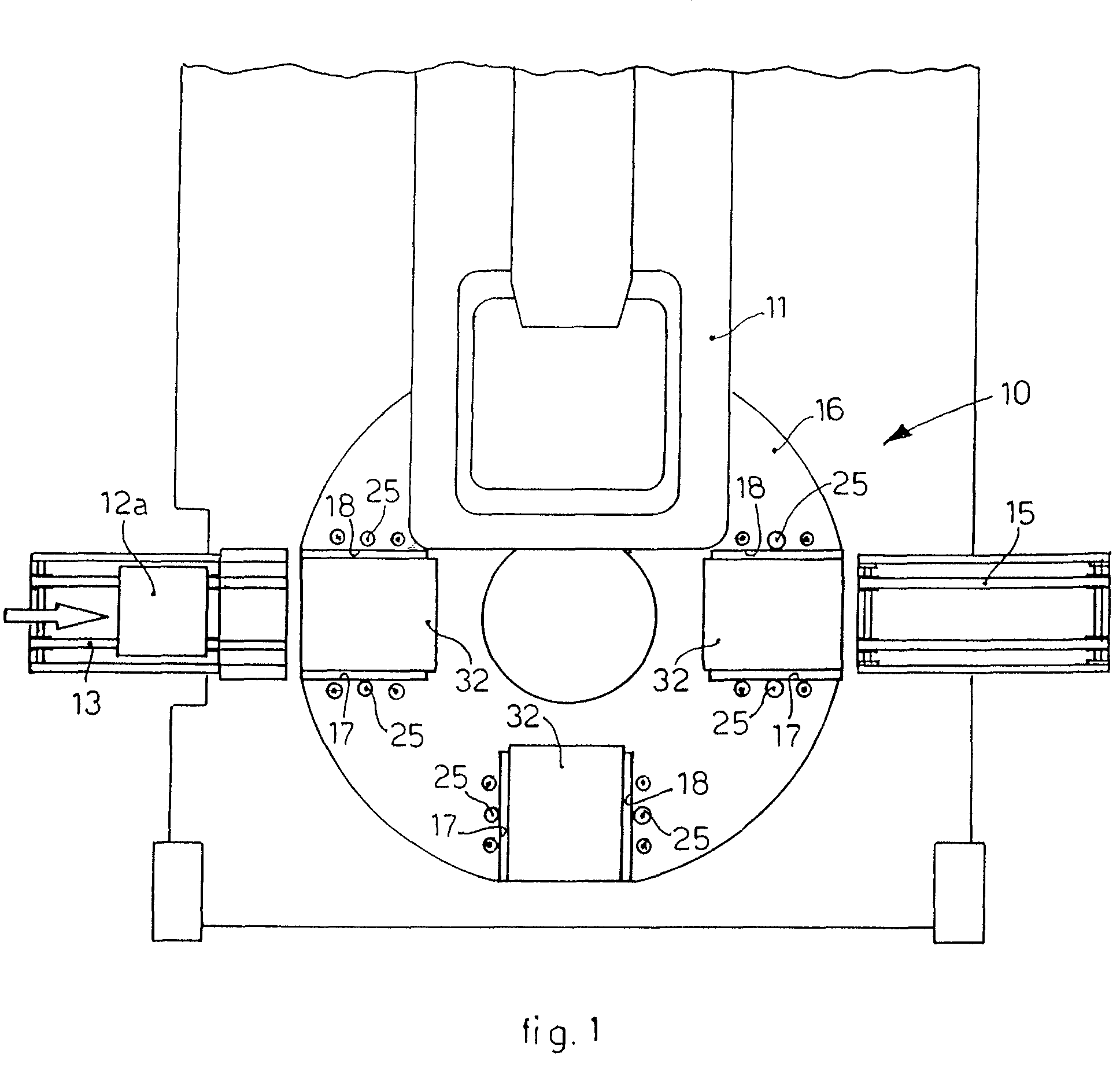
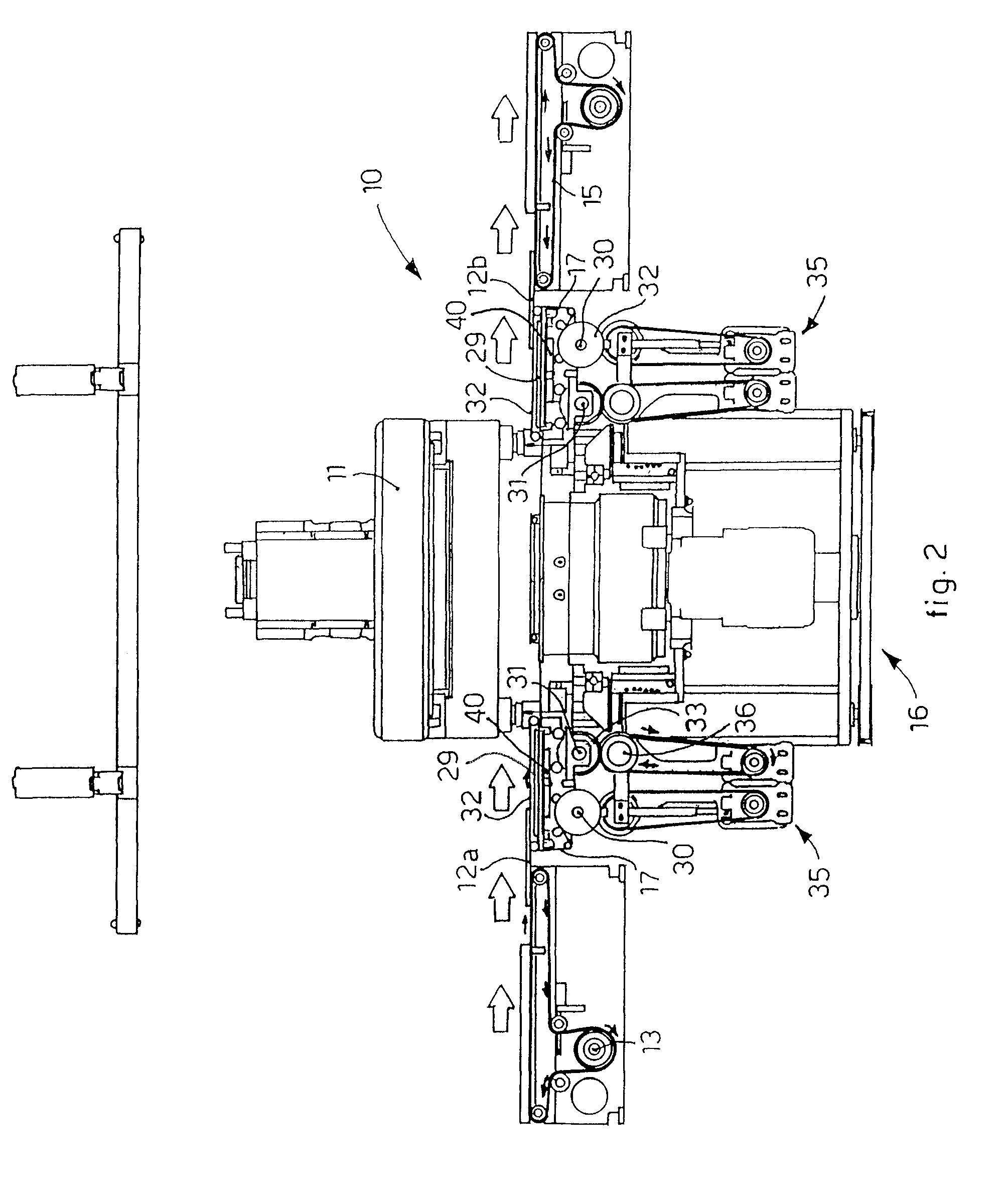
[0037]With reference to the attached drawings, a positioning device 10 according to the present invention is mounted on a metal deposition unit 11 of a plant for the production, in this case, of photovoltaic cells 12b starting from a silicon based wafer 12a.

[0038]The wafers 12a and the photovoltaic cells 12b are moved and positioned with respect to the metal deposition unit 11 by means of: a first conveyor belt 13 that feeds the wafers 12a; a second conveyor belt 15 that discharges the photovoltaic cells 12b; and a rotating turret 16 interposed between the two belts 13 and 15, which, as will be explained hereafter, carries, in a carousel manner, the wafers 12a and the photovoltaic cells 12b between the various operating positions.

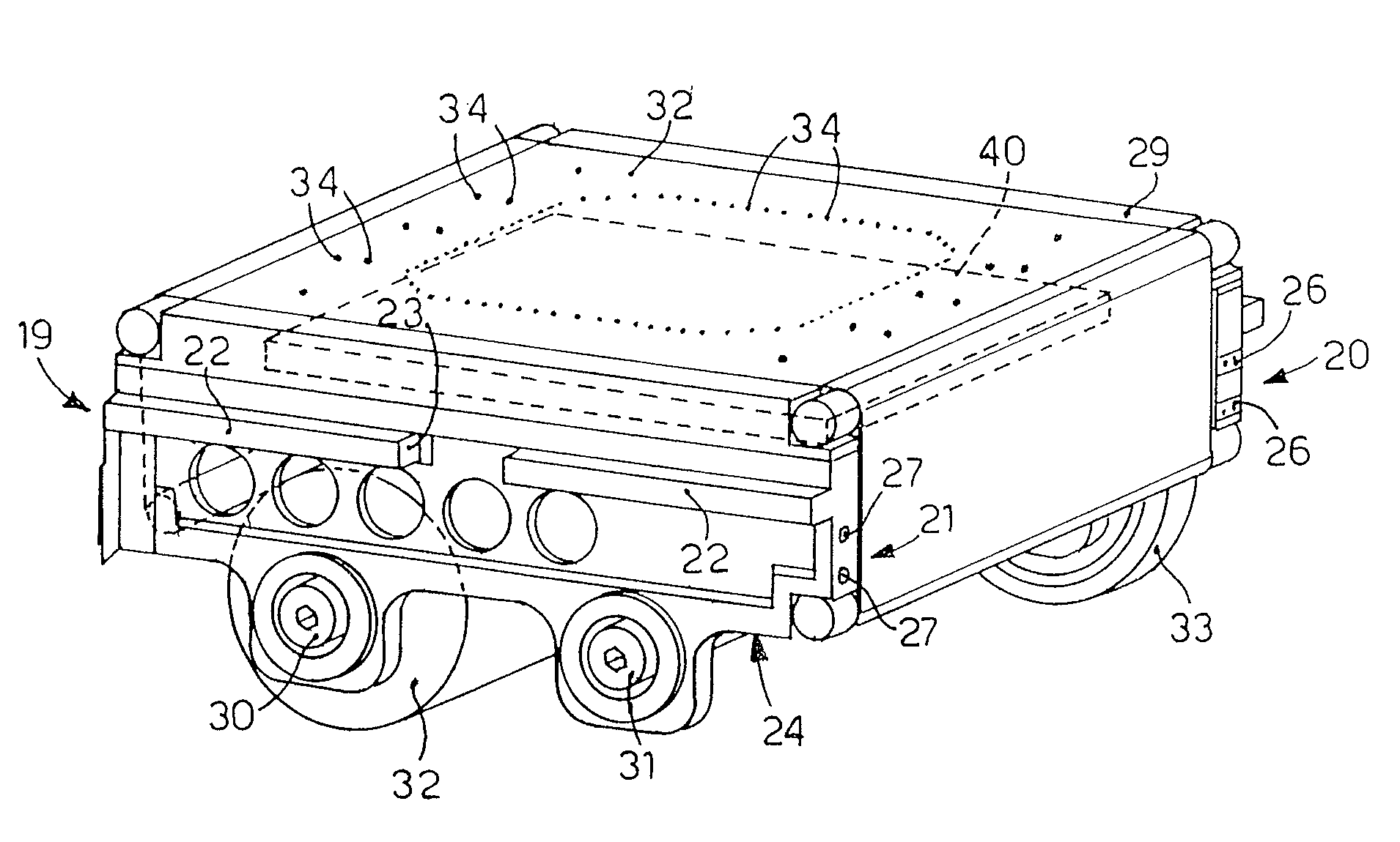
[0039]The positioning device 10 comprises one or more positioning members 17, in this case four, angularly offset at about 90° with respect to each other, and mounted on the rotating turret 16 by means of a removable frame 24, inside coordinated assembly s...


PUM

PropertyMeasurementUnit
movementaaaaaaaaaa
vacuum pressureaaaaaaaaaa
temperatureaaaaaaaaaa

Abstract

A positioning device to position one or more plates of electronic circuits with respect to an operating unit. The device comprises a rotary member which rotates selectively between a first operating position and a second operating position, and a positioning member mounted on the rotary member. The positioning member comprises a frame, which is mounted removably on the rotary member, and a strip of transpirant material on which each plate is rested. The strip is wound between a pair of winding / unwinding rollers, pivoted on the frame. The positioning member also comprises heating means able to heat the wafer to take it to a determinate operating temperature.

Description

FIELD OF THE INVENTION[0001]The present invention concerns a device to position plates for electronic circuits, for example green tape, silicon based wafers for photovoltaic cells, in a metal deposition unit, for example by means of silk-screen printing. In particular, the positioning device according to the present invention is applied to a transport member, for example a rotating turret, or a carousel, which carries the plates from a loading station to a discharge station, passing through at least a metal deposition station.BACKGROUND OF THE INVENTION[0002]Plants are known for working plates of electronic circuits, for example wafers for the production of photovoltaic cells, which comprise at least a unit to deposit metal tracks on the plates and a positioning device that positions and transports the plates with respect to the deposition unit, and other possible work stations.[0003]A positioning device is known, which comprises at least a feed belt to feed the plates and a rotatin...

Claims


Application Information

Patent Timeline
Patent Type & Authority Patents(United States)
IPC IPC(8): B23P19/00
CPCH01L21/67103H01L21/6715H01L21/67207H01L21/67715H01L21/67736H01L21/68764H01L21/68771H01L31/022425H01L21/67109Y10T29/53265H05K3/1216Y02E10/50Y10T29/53261Y10T29/5327Y10T29/49117Y10T29/532
Inventor BACCINI, ANDREA
Owner APPLIED MATERIALS ITALIA SRL
Why Eureka
Try Eureka