Systems and methods for valvular regurgitation detection

a technology of valvular regurgitation and detection method, applied in the field of implantable medical devices, can solve the problems of blood leakage, turbulence near the mitral annulus, blood leakage backward through the tricuspid valve,

Active Publication Date: 2012-01-31
CARDIAC PACEMAKERS INC
View PDF471 Cites 14 Cited by
  • Summary
  • Abstract
  • Description
  • Claims
  • Application Information

AI Technical Summary

Problems solved by technology

A defective or partially closed mitral valve can cause blood to leak and cause turbulence near the mitral annulus.
Improper atrial-ventricular delay (AV delay) can cause left ventricular dyssynchrony, which can lead to a partially closed mitral valve, in turn causing MR.
A defective or partially closed tricuspid valve can cause blood to leak backward through the tricuspid valve.
VR can make it difficult for the heart to increase blood flow during times of higher demand, such as during exercise.
It is believed that MR increases with congestive heart failure decompensation.
A mitral valve or tricuspid valve of a heart can become damaged through infection or disease.
Certain diet medications have been known to cause valvular damage.
Chronic MR may lead to severe left ventricle dysfunction, chronic congestive heart failure, or atrial fibrillation.
When an electrical signal is analyzed over a finite length of time, two problems can result.
The first problem is time localization.
Because the shape of the electrical signal waveform is highly dependent on the window of time used to sample the electrical signal, a window that is too long in time can cause localized time information in the electrical signal to be overlooked due to too much data or due to under-sampling of the signal.
The second problem is frequency localization.
If the window is too short there may be too few oscillations to determine localized frequency information in the electrical signal.
The main problem with the STFT is the inconsistent treatment of different frequencies; at low frequencies there so few oscillations within the window that it is not possible to extract localized frequency information, while at high frequencies there are so many oscillations that localized time information is lost.
One cause of VR is dyssynchrony of contractions of the chambers of the heart.

Method used


Image

  • Systems and methods for valvular regurgitation detection
  • Systems and methods for valvular regurgitation detection
  • Systems and methods for valvular regurgitation detection

Examples


Embodiment Construction

[0020]In the following detailed description, reference is made to the accompanying drawings which form a part hereof, and specific embodiments in which the invention may be practiced are shown by way of illustration. It is to be understood that other embodiments may be used and structural or logical changes may be made without departing from the scope of the present invention.

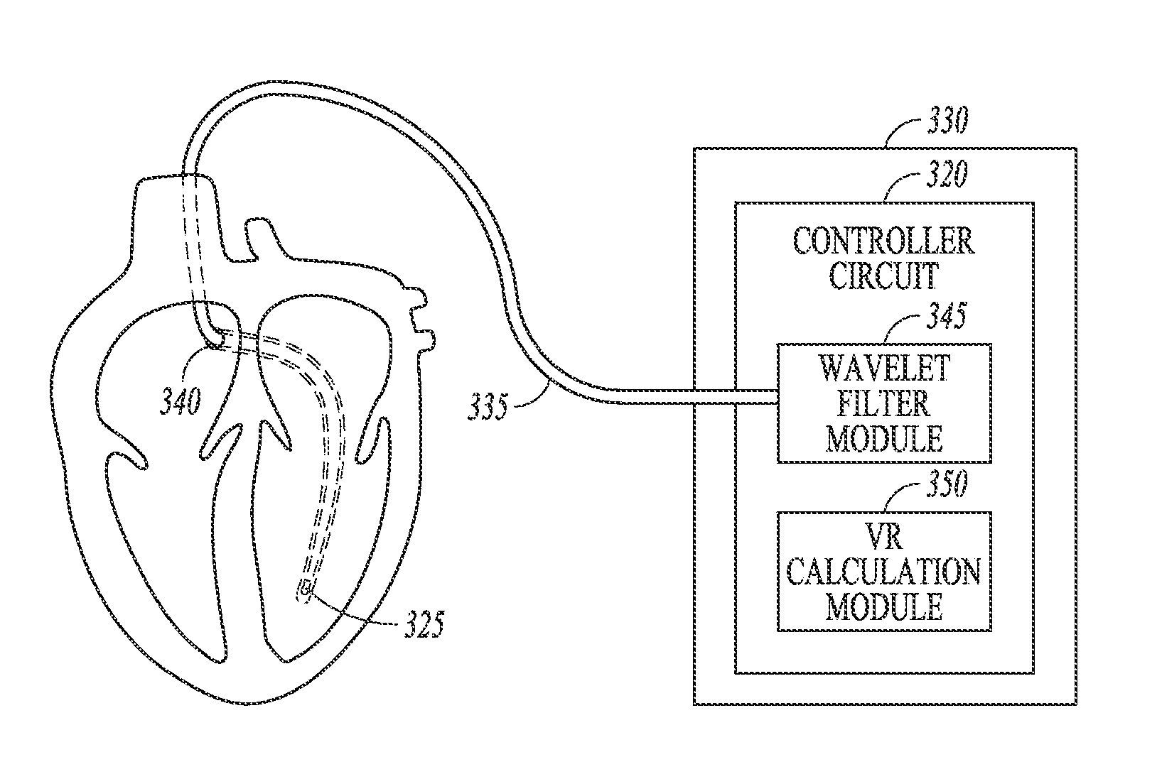
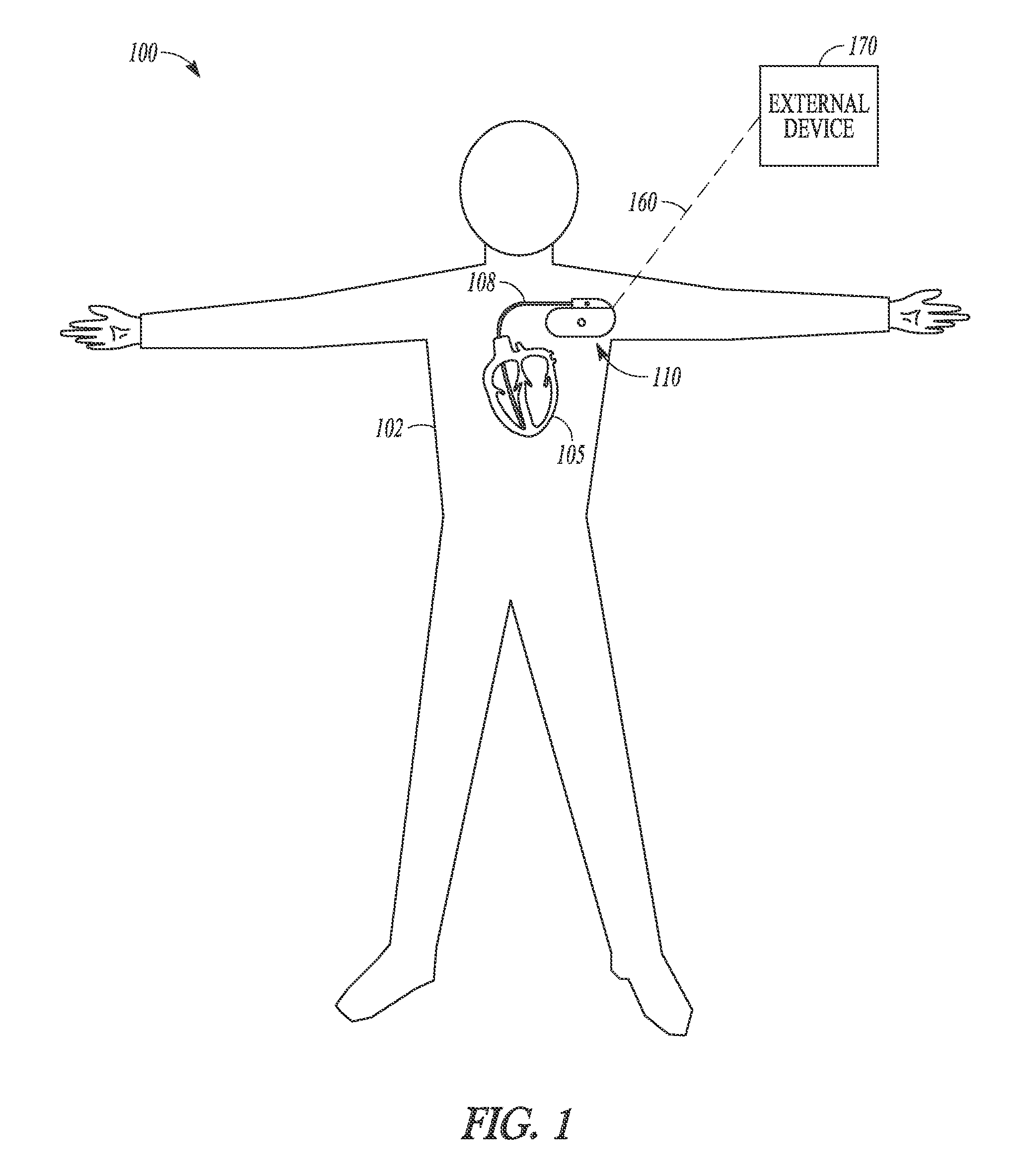
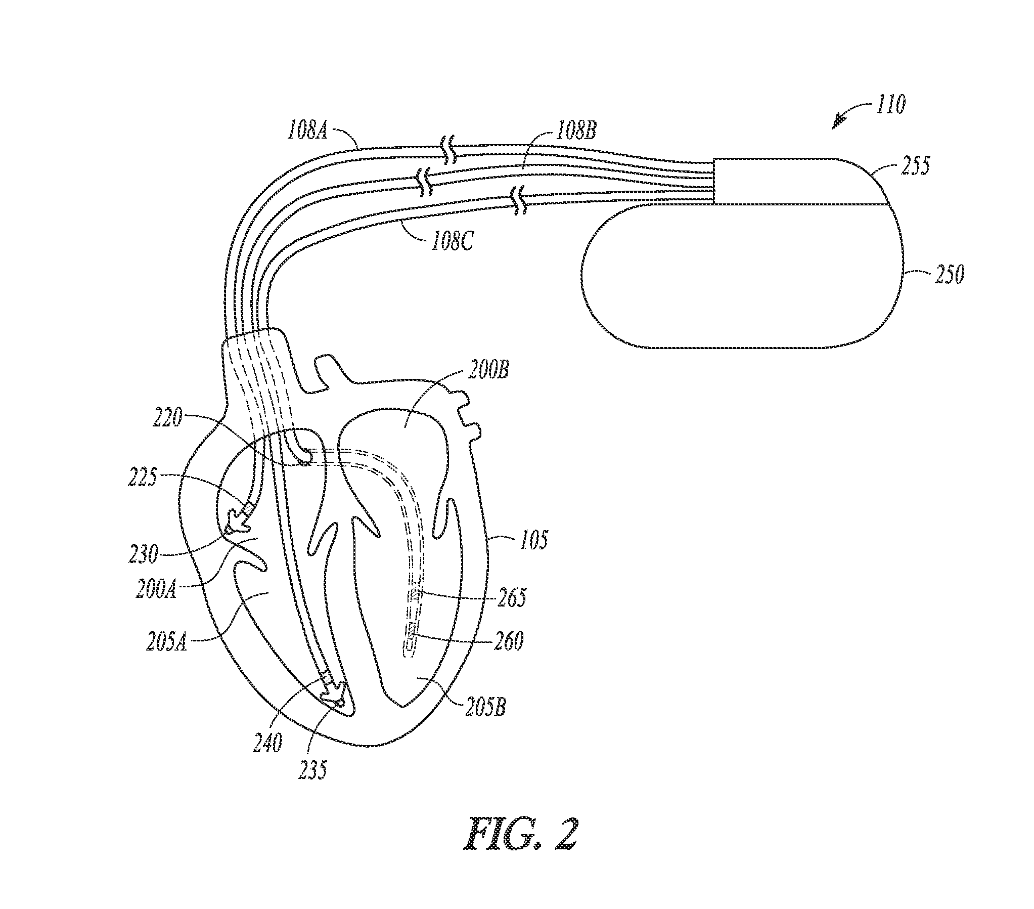
[0021]Valvular regurgitation (VR) is manifested as a turbulent blood flow in the left or right atrium or near the aortic valve during systole. VR refers to mitral regurgitation (MR), or tricuspid regurgitation (TR), or aortic regurgitation (AR), or a combination of two or more of MR, TR, and AR. Some amount of VR is believed present during early systole in eighty percent of patients exhibiting interventricular dyssynchrony between their right and left ventricles. Sensors can be included in implantable medical devices (IMDs) to provide internal patient diagnosis. The output from one or more sensors appropriate t...


PUM


Abstract

A system comprising an implantable medical device (IMD). The IMD includes an implantable sensor operable to produce an electrical signal representative of mechanical activity of a heart of a subject and a controller circuit coupled to the sensor. The controller circuit includes a wavelet filter module and a valvular regurgitation (VR) calculation module. The wavelet filter module is configured to extract signal energy information from the electrical signal. The energy information includes variation of signal amplitude with frequency and time. The VR calculation module is configured to calculate a measurement of VR for one or more heartbeats using the energy information.

Description

CROSS-REFERENCE TO RELATED APPLICATIONS[0001]This application is related to the following, commonly assigned U.S. Patent Applications: Ser. No. 10 / 900,570 entitled “DETERMINING A PATIENT'S POSTURE FROM MECHANICAL VIBRATIONS OF THE HEART,” filed on Jul. 28, 2004, now issued as U.S. Pat. No. 7,559,901; Ser. No. 10 / 703,175, entitled “A DUAL USE SENSOR FOR RATE RESPONSIVE PACING AND HEART SOUND MONITORING,” filed on Nov. 6, 2003, now issued as U.S. Pat. No. 7,248,923; Ser. No. 10 / 334,694 entitled “METHOD AND APPARATUS FOR MONITORING OF DIASTOLIC HEMODYNAMICS,” filed on Dec. 30, 2002, Ser. No. 10 / 746,874 entitled “A THIRD HEART SOUND ACTIVITY INDEX FOR HEART FAILURE MONITORING,” filed on Dec. 24, 2003, now issued as U.S. Pat. No. 7,115,096; Ser. No. 11 / 037,275, entitled “METHOD FOR CORRECTION OF POSTURE DEPENDENCE ON HEART SOUNDS,” filed on Jan. 18, 2005, now issued as U.S. Pat. No. 7,662,104; Ser. No. 60 / 631,742 entitled “CARDIAC ACTIVATION SEQUENCE MONITORING FOR ISCHEMIA DETECTION,” f...

Claims


Application Information

Patent Timeline
Patent Type & Authority Patents(United States)
IPC IPC(8): A61N1/00
CPCA61N1/3627A61N1/36578A61B7/04
Inventor PATANGAY, ABHILASHSIEJKO, KRZYSZTOF Z.
Owner CARDIAC PACEMAKERS INC
Why Eureka
Try Eureka