Device for treatment of valve regurgitation

a technology for valve regurgitation and implantable devices, which is applied in the field of implantable devices for treating heart valve regurgitation, can solve the problems of serious health diseases such as regurgitation, heart failure and death of patients, and patients' heart failure and death, and achieve the effect of effective treatment methods

Inactive Publication Date: 2020-03-05
SHANGHAI JOY MEDICAL DEVICES CO LTD
View PDF0 Cites 2 Cited by
  • Summary
  • Abstract
  • Description
  • Claims
  • Application Information

AI Technical Summary

Benefits of technology

[0021]Preferably, the linker and the anchor are connected by an elastic material or a hinge with certain degree of freedom; so the anchoring device allows swinging or rotating the frame in the native valve orifice. When the anchor is arranged at the apex or between the papillary muscles near the apex, an apex snap ring is provided outside of apex for preventing the anchor from moving, and the snap ring can bear the tension and pressure from the linker.
[0030]The technical benefits of the present disclosure are as follows: (1) The device of the present disclosure has prosthetic valve inside the occluder, comparing with a occluder, it reduces the flow resistance during diastole, and effectively decrease the risk of thrombosis; the native heart valve leaflets coaptate on the outer surface of the occluder and the prosthetic valve in the occluder also closes during systole, therefore the device has minimal interference with the native valve annulus for better ventricular function. (2) The device of the present disclosure has the advantages of simple structure, accurate positioning, small size, is suitable for various types of mitral / tricuspid regurgitation patients; by designing appropriately with minor modification of sizing, it can be used in children to high-risk elderly patients and is also applicable for treatment of valve prolapse. (3) The device of the present disclosure has little interference with the native valve annulus, it also helps to shorten the learning process for surgeon who often needs to correctly engage other devices to the native valve annulus.

Problems solved by technology

Mitral regurgitation will cause pulmonary congestion and hypertrophy of left ventricle 3, eventually leading to heart failure and death in patients.
Mitral regurgitation will cause pulmonary congestion and left ventricular hypertrophy, eventually leading to heart failure and death of patients, so mitral regurgitation is a serious health disease.
However, there is no practical way to treat mitral regurgitation in patients who are unsuitable for thoracotomy or open heart surgery.
The MitraClip on the market is a proven repair device for the treatment of mitral regurgitation, but it is only suitable for relatively few patients, usually those patients with regurgitation caused by mitral valve prolapse, who still have residual regurgitation, whereas for patients with ischemic mitral regurgitation, the treatment is not effective.
Furthermore, the sub-annular structure may enlarge and calcify, have a risk of chordal rupture chordal rupture.
Interventional prosthetic valve replacement methods also have numerous difficulties, such as the placement of an anchoring device on an expanded native valve annulus, which can sometimes cause the annulus to expand further.
Large valves often reduce durability of prosthetic valves significantly.
With regard to those methods for reducing the size of the dilated annulus, an interventional annuloplasty ring in the minimally invasive prosthetic devices is less stable than its application of open-heart operation.
Therefore, suitable replacement / anchoring devices are all very challenging and affect the application efficacy of this device.
All of the devices described above have one thing in common: these minimally invasive methods of treating valve regurgitation have significant, unpredictable effects on native structures of valves and valve annuli.
Due to the special physiological structure and complex physiological environment of the mitral annulus and tricuspid annulus, relevant treatment has great difficulties in achieving relatively good therapeutic effect, as well as positioning and fixation at the same time.
In view of the problem treating mitral and tricuspid insufficiency in the prior art, transcatheter prosthetic valve replacement requires a large anchoring ring, affects the service life of the prosthetic valve and affects the function of the valve itself; although valve plug coaptation plate technology can prohibit backflow effectively, it would restrict the flow of blood when the valve opens, resulting in mitral or tricuspid stenosis, and increasing risk of thrombosis in patients.

Method used


Image

  • Device for treatment of valve regurgitation
  • Device for treatment of valve regurgitation
  • Device for treatment of valve regurgitation

Examples


embodiment 1

[0051]A device for treating mitral regurgitation, comprises a frame and an anchoring device with the anchoring device being connected to the frame.

[0052]Frame

[0053]The frame is placed in the native mitral valve leakage gap by an anchoring device when the mitral valve is closed, the frame being expanded at the gap, the native valve leaflets being in close contact with the outer surface of the frame when it is closed. The frame has an inflow end and an opposite outflow end. The frame acts as a supporting structure for a prosthetic valve in the frame and makes the entire device compressible and expandable.

[0054]In vitro, the device is compressed into the catheter, and upon reaching a predetermined position of the native valve orifice, the device is pushed out to self-expand back to its originally designed expanded state and is anchored by the anchoring device.

[0055]The outflow end of the frame is preferably tapered relative to the inflow end, which occupies less space and facilitates t...

embodiment 2

[0091]As shown by 101 to 106 in FIG. 10, the shape of cross-section in the short axis plane of the frame is an irregular combination of arcuate edges and may continuously vary from the inflow end to the outflow end of the frame, so as to fit different gaps between native valve leaflets during systole.

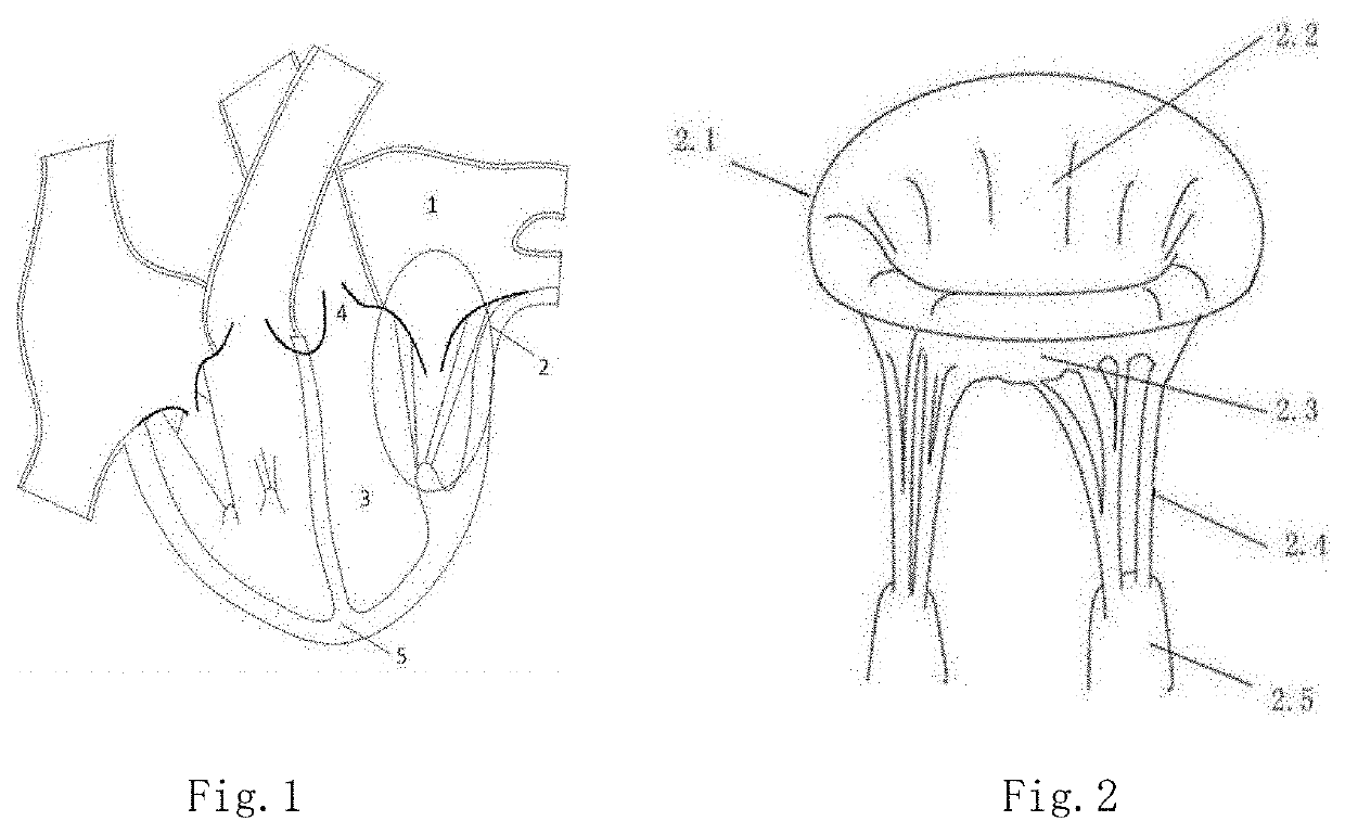
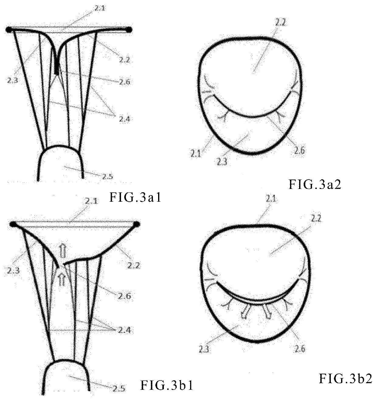
[0092]As shown in FIG. 10, is the cross-section of the frame in relationship to the native valve leaflets, in which 2.2 is the anterior leaflet and 2.3 is the posterior leaflet. In this case, the distribution of the gap 116 in the mitral regurgitation is not uniform; The gap is narrow in the middle, while the gaps at both sides may be irregular and may become rather large. Different from Embodiment 1, the shape 105 of the preferred cross-section of the embodiment of the present embodiment assumes a crescent-like shape. Its central portion has an arc with a height narrower than its two ends, and its two ends are rounder and larger. When the frame is in contact with the native valve leafl...

embodiment 3

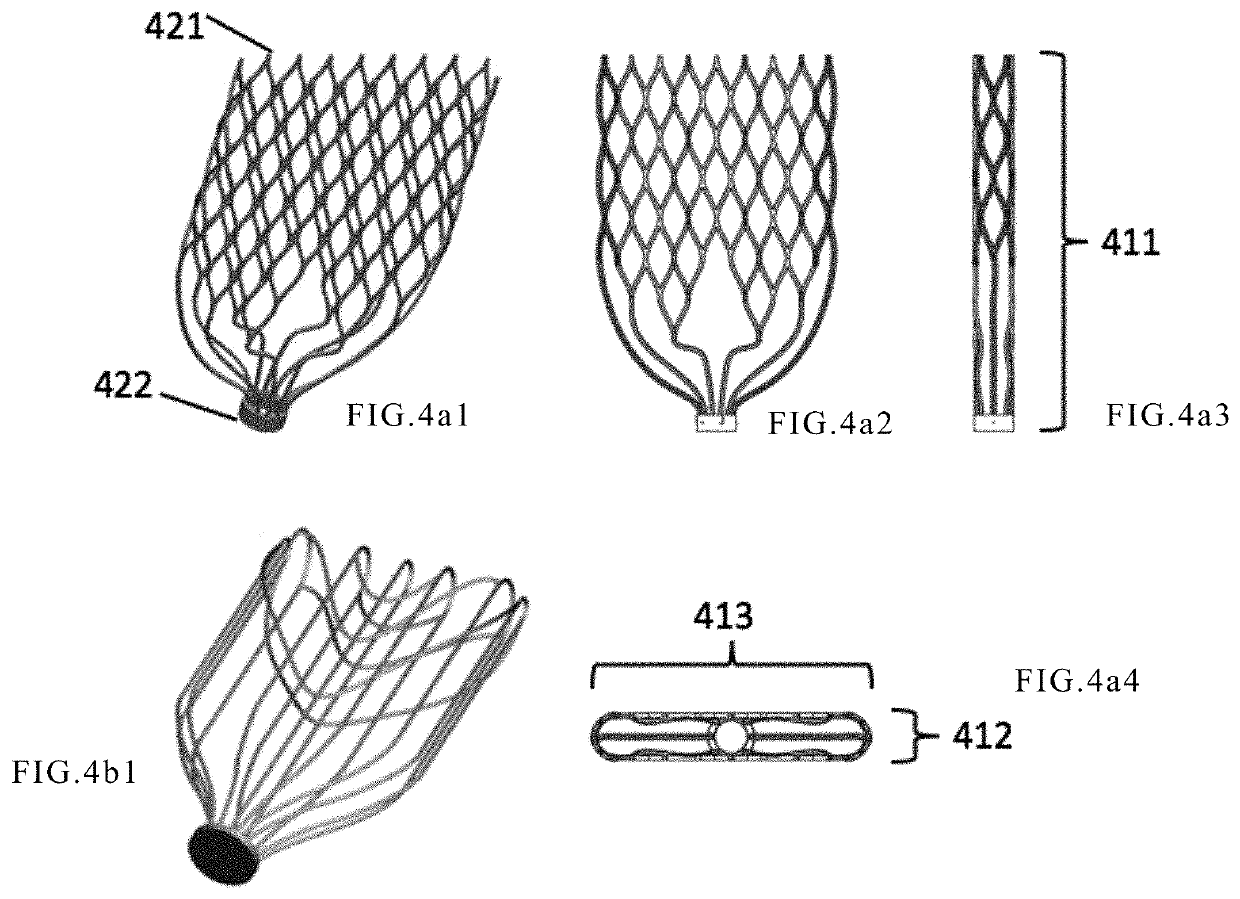
[0093]Different from Embodiment 1, the anchor further includes an anchor mechanism involved with a lattice structure arranged inside the atrium, similar to the shape of a cage. The shape of the anchor can be adapted to the anatomy of the left atrium; so to allow positioning the frame at the desired location. The frame may be a lattice structure in a cylinder. When the inner diameter of the cylinder is large enough, it may displace the native valve to become a valve replacement. The distal end of the anchoring cage is connected to the inflow end of the frame, and may be connected by an elastic metal wire, such as a Ni—Ti alloy wire. The anchoring device, with elements including the linker supporting rod and the anchor as shown in the Embodiment 1, and the like, may be placed in the ventricle at the same time. As shown in FIG. 11, the anchoring device includes an intra-atrial lattice-like anchoring cage 132, a cylindrical lattice frame 133, and an intra-ventricular linker supporting r...


PUM


Abstract

A device for treatment of valve regurgitation is described, comprising frameworks (114, 133, 141, 701, 812, 821, 911) and an anchoring unit (132). The anchoring unit (132) is connected to the frameworks (114, 133, 141, 701, 812, 821, 911); the frameworks (114, 133, 141, 701, 812, 821, 911) can be expanded and compressed and have an inflow end (421) and an opposite outflow end (422); valve leaflets (142, 621, 721, 751) capable of opening and closing in blood flow are provided inside the frameworks (114, 133, 141, 701, 812, 821, 911); the anchoring unit (132) can keep the frameworks (114, 133, 141, 701, 812, 821, 911) in an expanded state at the orifice position of a natural heart valve. The device for treatment of valve regurgitation and an implantation method therefor can effectively treat valve regurgitation.

Description

TECHNICAL FIELD[0001]The present disclosure pertains to the field of cardiovascular medical devices, and in particular to an implantable device for treating heart valve regurgitation, and methods of implanting the same.BACKGROUND OF THE INVENTION[0002]A mammalian heart contains four chambers as shown in FIG. 1, two atriums as the chambers for inflowing and two ventricles as the chambers for pumping out. The left ventricle 3 is located at the top left of apex 5, the mitral valve 2 is located between left atrium 1 and left ventricle 3, and the mitral valve 2 controls the unidirectional flow of blood from left atrium 1 to left ventricle 3. A dysfunctional mitral valve 2 will render two leaflets of the mitral valve 2 to close incompletely, causing blood to backflow from left ventricle 3 to left atrium 1 during systole. Mitral regurgitation will cause pulmonary congestion and hypertrophy of left ventricle 3, eventually leading to heart failure and death in patients. The structure of the ...

Claims


Application Information

Patent Timeline
Patent Type & Authority Applications(United States)
IPC IPC(8): A61F2/24
CPCA61F2/2457A61F2/2418A61F2/2427A61F2230/0017A61F2/246A61F2/2466A61F2230/0069A61F2/2412A61B2017/00243A61F2/2463A61F2210/0014A61F2250/0039A61F2/07A61F2250/0069A61F2250/0017
Inventor LEE, SHOUYANNAN, HONGXIA
Owner SHANGHAI JOY MEDICAL DEVICES CO LTD
Why Eureka
Try Eureka